Royal Foam Technical Center:
Documentation, Specifications & Instructions
Everything architects, installers, designers, and procurement managers need to specify, approve, and install with confidence.
Use the filter to find relevant document
Themed Backdrops and Environments

Catalog of decorative panels 1
Catalog of decorative panels
Catalog of decorative panels
Catalog of decorative panels
catalog
catalog
catalog
Filters
- Select All
- DWG (1)
- PDF (2)
- Select All
- Catalogs (2)
- Select All
- 3D letters (1)
- logos (1)
Recommended Video
Custom 3D Letters & Props
Custom 3D Letters & Props
Monument Sign Projects
Monument Sign Projects
Custom Foam Letters, Stages & Monuments by 3D Fabrication Studio
Custom Foam Letters, Stages & Monuments by Royal Foam
Where bold imagination meets lightweight durability

System Architecture
vs. Conventional Materials
| Component | Description | Value | Unit | Standard/Code | Impact | Application | Notes |
|---|---|---|---|---|---|---|---|
| EPS Core | Primary shaped body | 1.0 / 2.0 | lb/ft³ | ASTM C578 | Defines weight + compressive behavior | All EPS products | Royal Foam working density |
| Adhesive Layer | Laminates foam sections | Construction-grade | system | Manufacturer spec | Prevents separation of parts | Built-up products | Use compatible foam-safe adhesive |
| Polyurea Shell | Primary hard protective coat | 30–60 | mil | Manufacturer spec | Impact, moisture, abrasion resistance | Exterior products | Royal Foam working thickness |
| Base Primer | Promotes coating bond | 1 coat | layer | Manufacturer spec | Improves adhesion | Before polyurea | Required by coating system |
| Finish Coat | Paint or decorative finish | 2 coats | layer | Paint spec | UV resistance + final appearance | Exterior/interior | Color depends on project |
| Products | Top architectural element | Custom | dimension | Project drawings | Visual hierarchy | Classical/custom products | Can be foam-built or composite |
| Products | Main cylindrical/tapered body | Custom | dimension | Project drawings | Main visible mass | Round/square/tapered products | CNC-shaped |
| Products | Bottom transition element | Custom | dimension | Project drawings | Visual stability + clean termination | All products | Sized to field conditions |
| Mechanical Anchoring | Attachment to substrate | Project-specific | detail | Engineer of record / FBC | Resists wind and service loads | Exterior products | Depends on wall/frame condition |
| Sealant at Joints | Weather sealing at seams | Exterior-grade | system | Sealant spec | Helps block water intrusion | Segment joints | Important in Florida exposure |
| Wind Resistance | Assembly performance target | 120–180 | PSF | Florida Building Code / project engineering | Affects fastening design | Exterior use | Depends on geometry + anchorage |
| Service Life | Expected lifespan when properly built | 15–25+ | years | Industry practice | Supports lifecycle value | Commercial/residential | Requires maintenance of finish |
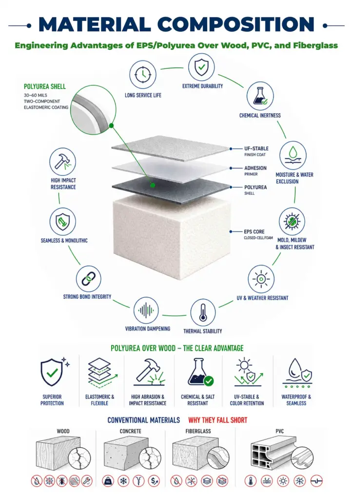
Integrated Multi-Layer System
Our company’s architectural products are engineered as a fully integrated system composed of:
- EPS Core: 1.0–2.0 lb/ft³ density
- Polyurea Coating: two-component, 30–60 mils
- Adhesion Primer
- UV-Stable Finish Coat
Core Philosophy
This is not a sequence of separate layers. It is a closed engineered envelope where every component has a defined structural or protective role.
Functional Role of Each Layer
- EPS Core: Provides geometric form. Maintains dimensional stability. Reduces total weight.
- Polyurea Shell: Adds mechanical resistance. Provides chemical inertness. Blocks moisture intrusion.
- Primer Layer: Ensures bond integrity between materials.
- Finish Coat: Protects against UV exposure. Stabilizes final appearance.
Why Conventional Materials Fall Short
- Wood: Vulnerable to moisture and decay. Requires constant maintenance. Can structurally degrade in 3–7 years in harsh climates.
- Fiberglass: Dependent on rigid molds. Limited to prefabricated shapes. Custom designs become expensive.
- PVC: Thermal expansion: $5–8 \times 10^{-5}/°C$. Can warp, open joints, and lose dimensional accuracy under temperature swings.
- Precast Concrete / Natural Stone: Extremely heavy. Requires cranes and reinforced substrates. Slower, more complex installation process.
Performance Advantages of Our Company
- CNC Precision: ±3 mm across any profile.
- Weight Reduction: 60–80% lighter than reinforced concrete.
- Faster Installation: No heavy lifting equipment required.
- Lower Structural Load: Reduced dead load on building envelope.
- Wind Resistance: 120–180 PSF.
- Code Engineering: Designed to Florida Building Code requirements.
- Permit Ready: Substrate-specific anchorage by licensed engineer.
Final Result
Our company is not a decorative surface treatment. It is a fully documented, engineered, permit-ready architectural system designed to move efficiently from fabrication to installation without rework.
Material Composition
| Layer / material | Description | Value | Unit | Standard/Code | Impact | Application | Notes |
|---|---|---|---|---|---|---|---|
| EPS Type I | Lightweight core option | 1.0 | lb/ft³ | ASTM C578 | Lower weight, easier handling | Non-critical decorative volumes | Economical option |
| EPS Type II | Denser core option | 2.0 | lb/ft³ | ASTM C578 | Higher compressive performance | Higher-abuse / larger elements | Preferred for stronger assemblies |
| Closed-cell EPS | Foam cell structure | Closed-cell | type | ASTM C578 | Low water absorption compared with open-cell foams | Exterior/interior | Royal Foam technology |
| Polyurea Coating | Elastomeric hard coat | 30–60 | mil | Manufacturer spec | Primary durability layer | Exterior elements | Royal Foam working range |
| Polyurea Chemistry | Fast-set sprayed coating | 2-component | system | Manufacturer spec | Rapid cure for production | Coated EPS parts | Requires proper prep |
| Primer | Surface preparation layer | 1 coat | layer | Manufacturer spec | Promotes coating bond | Before polyurea | Do not skip CNC-shaped |
| Paint / Finish | UV-stable decorative finish | 2 coats | layer | Paint spec | Color retention + aesthetics | Visible surfaces | Final appearance depends on finish system |
| Adhesive | Foam-safe joining material | Project-specific | system | Manufacturer spec | Section bonding | Multi-part assemblies | Must be coating-compatible |
| Sealant | Flexible weather joint material | Exterior-grade | system | Sealant spec | Moisture defense at seams | Field joints | Important for Florida rain exposure |
| Optional Reinforcement | Internal rods/plates/brackets | Project-specific | detail | Engineer of record | Improves anchorage / load transfer | Large or special elements | Not every element needs it |
| Fasteners / Anchors | Attachment hardware | Project-specific | detail | FBC / engineer | Critical to actual wind performance | Exterior installation | Substrate matters |
| Surface Texture | Smooth / stone / custom effect | Custom | finish | Project spec | Controls visual style | Architectural applications | Supports premium positioning |
Engineered Composite System
Our company’s products are built on a composite material architecture that no single conventional material can replicate.
Core Structure
- EPS TYPE I: 1.0 lb/ft³ density
- EPS TYPE II: 2.0 lb/ft³ density
- Standards: Classified under ASTM C578
- Material: Closed-cell EPS foam
- Moisture Resistance: Water absorption below 2% per ASTM C272
Why It Matters
This low absorption threshold is critical for facade elements exposed to:
- Wind-driven rain
- Condensation cycles
- Sustained humidity
Protective Outer Shell: Two-Component Polyurea Coating
- Applied Thickness: 30–60 mils
- Shore D Hardness: 40–70
- Durability: High impact and abrasion resistance
- Chemistry: Chemical inertness
Performance Benefit:
Far exceeds conventional paints and gelcoats in durability and service resistance.
Technical Comparison with Competing Materials
- WOOD: Hygroscopic by molecular structure. Shrinks, warps, and separates under wet/dry cycles. Vulnerable to fungi and insects. Structural degradation in 5–10 years in warm humid climates.
- ENGINEERED LUMBER: Reduces variability, but remains moisture-sensitive and biologically vulnerable.
- PVC: Loses 30–40% elastic modulus above 40°C (104°F). Creeps under self-weight and wind pressure. UV causes embrittlement and pigment breakdown in 7–10 years.
- FIBERGLASS: Often lacks third-party certified data in custom fabrication. Gelcoat damage allows hidden water intrusion. Internal delamination may remain invisible until failure.
Failure Modes Eliminated by Royal Foam
Our company EPS + Polyurea removes all common substrate failures:
- No cellulosic substrate to rot
- No metal components to corrode
- No thermoplastic matrix to creep
- No laminate interface to delaminate
Long-Term Client Value (Delivered Performance)
- Projected Service Life: 15–25+ years
- Maintenance Interval: 5–10 years
- Topcoat refinishing only
- ASTM-traceable performance data
- Based on documented standards, not marketing claims
Final Statement:
Our company is a measurable, testable, engineered exterior product system designed for long-term architectural performance.
Durability
| Factor | Description | Value | Unit | Standard/Code | Impact | Application | Notes |
|---|---|---|---|---|---|---|---|
| EPS Density | Core density affects dent resistance | 1.0 / 2.0 | lb/ft³ | ASTM C578 | Higher density improves robustness | All Products | 2.0 better where abuse is higher |
| Polyurea Thickness | Primary hard coat thickness | 30–60 | mil | Manufacturer spec | Major durability driver | Exterior Products | Royal Foam Working Range |
| Water Absorption | EPS water absorption | Low | qualitative | ASTM C272 | Helps in humid environments | Exterior/interior | System still needs sealed finish |
| Moisture Resistance | Coated system resists rain splash | High | rating | Finish system | Florida suitability | Exterior Products | Seams must be sealed |
| UV Exposure | Finish must resist sun degradation | Requires topcoat | system | Paint spec | Affects color life | Exterior in Florida | Polyurea should be topcoated |
| Impact Resistance | Coating helps resist minor impact | Medium to high | rating | Coating spec | Important at pedestrian level | Retail/commercial | Not equivalent to solid concrete |
| Crack Control | Joint detailing reduces cracking risk | Project-specific | detail | Installation best practice | Preserves appearance | Segmented builds | Movement joints may be needed |
| Abrasion Resistance | Hard shell resists scuffing | High | rating | Coating spec | Useful in touch-prone areas | Entry Products | Depends on finish quality |
| Biological Resistance | EPS does not rot like wood | High | rating | Material property | Lowers maintenance | Exterior/interior | Still protect finish required |
| Corrosion Resistance | Foam shell will not rust | High | rating | Material property | Advantage over unprotected steel skins | Humid/coastal areas | Anchors may still require protection |
| Maintenance Cycle | Repaint/reseal as needed | 5–10 typical | years | Paint maintenance | Extends service life | Exterior projects | Climate + color affect cycle |
| Service Life | Expected full-system life | 15–25+ | years | Industry practice | Supports lifecycle value | All Products | Assumes proper installation |
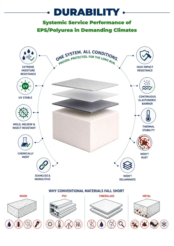
Warm, coastal, and high-humidity climates present a compound durability challenge for exterior architectural products: wind-driven rain, sustained UV exposure, biological growth, salt-laden air, and diurnal thermal cycling all operate simultaneously and without interruption for the full service life of the installation.
Any material selection that addresses only one or two of these mechanisms while remaining vulnerable to the others will produce premature failure.
Our company EPS/polyurea products are engineered to resist all active degradation mechanisms in parallel, not in sequence.
The polyurea coating at 30–60 mils functions as a continuous elastomeric barrier — no seams, no capillary channels, no porous zones through which moisture can migrate to the EPS core.
With Shore D hardness of 40–70, it resists pedestrian-level mechanical impacts (tool contact, equipment brushing, incidental loading) at a level unachievable with conventional latex paint or fiberglass gelcoat.
The EPS core is chemically inert: it does not provide a metabolizable carbon source for fungal or bacterial colonization, does not react with moisture, and does not contain ferrous components capable of corrosion.
When joints and terminations are properly detailed and sealed, the assembled system delivers high moisture resistance performance even under sustained wind-driven rain exposure.
Competing Materials Fail by Documented Mechanisms
- WOOD: Demands repainting every 3–5 years, chemical treatment against insect attack, and annual inspection for decay — cumulative 20-year maintenance expenditure routinely exceeds original installed cost.
- PVC: Embrittles and discolors under UV in 7–10 years; thermal expansion mismatches at joints create pathways for water infiltration.
- FIBERGLASS: Delaminates internally when the protective gelcoat is breached, a failure mode that is undetectable without non-destructive testing until visible surface collapse occurs.
Clients who specify our company products receive a warranted system service life of 15–25+ years, a predictable maintenance cycle of topcoat refinishing every 5–10 years, and resistance to biological, mechanical, UV, and moisture degradation that does not require the owner to manage multiple separate protection programs.
Compliance
| Requirement | Description | Value | Unit | Standard/Code | Impact | Application | Notes |
|---|---|---|---|---|---|---|---|
| EPS Material Standard | Foam classification | Type I / Type II | class | ASTM C578 | Defines density/performance baseline | All EPS parts | Use project-appropriate type |
| Water Absorption Test | Moisture behavior reference | Applicable | test | ASTM C272 | Supports durability documentation | Exterior use | Useful for submittals |
| Surface Burning | Fire performance reference | Classified by assembly | rating | ASTM E84 | Important in code review | Commercial/interior conditions | Depends on full assembly |
| Florida Wind Design | Wind exposure must be engineered | 120–180 | PSF | Florida Building Code | Critical for exterior approval | Florida projects | Final value depends on site + anchorage |
| Anchorage Design | Fasteners and substrate must be checked | Project-specific | detail | FBC / engineer of record | Real compliance is in attachment | Exterior elements | Do not rely on foam alone |
| IBC Coordination | General building code coordination | Required | status | IBC as adopted locally | Ensures broader code consistency | Commercial work | Use local jurisdiction requirements |
| Flame Retardant EPS | Where required by spec/code | Specify as needed | status | Project spec | Supports fire-related compliance strategy | Commercial/interior use | Verify exact project requirement |
| Permit Drawings | Dimensions + attachment details | Required | status | Permit process | Needed for approvals | Commercial / HOA / municipal | Prepare submittal set |
| Engineering Review | Stamped review when required | Required by project | status | Engineer of record | Reduces approval risk | Florida exterior work | Especially high-wind zones |
| Sealant / Joint Detailing | Weather management in assembly | Required | status | Best practice / project spec | Affects envelope behavior | Exterior joints | Not optional in exposed conditions |
| Accessibility / Clearance | Products must not conflict with circulation | Project-specific | detail | IBC/ADA as applicable | Field coordination issue | Walkways/entries | Depends on placement |
| Local Jurisdiction Review | County/city interpretation varies | Required | status | Local AHJ | Must be checked early | All permitted work | Never assume one-size-fits-all |
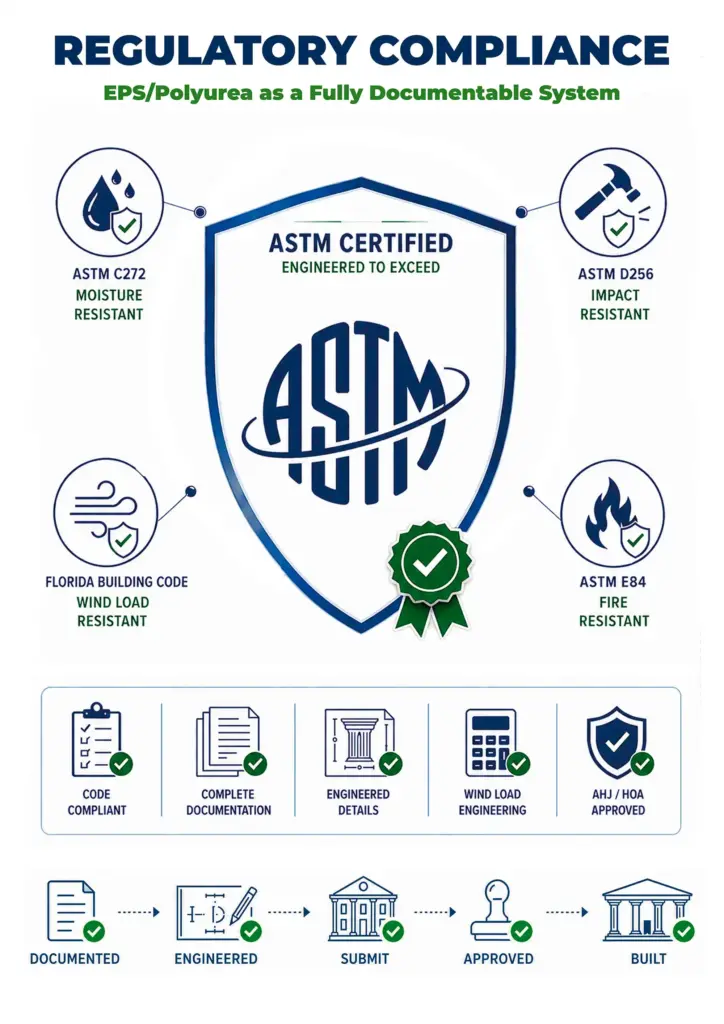
REGULATORY APPROVAL OF EXTERIOR ARCHITECTURAL ELEMENTS IS NOT A FORMALITY — it is a critical path item in the construction schedule.
Risk Factors:
A rejection from the Authority Having Jurisdiction (AHJ), a request for additional engineering data from the HOA, or a code-compliance question from the plan reviewer can delay a project by weeks, trigger contract penalty clauses, and require the design team to produce documentation under time pressure.
Strategy:
Selecting a material system with a complete, pre-existing compliance package is a direct risk mitigation strategy for the owner, developer, and general contractor.
Technical Standards & Submittals
ASTM Standards:
- ASTM C578 classifies EPS foam by type and provides numerical values for density, compressive resistance, flexural strength, and thermal conductivity — the language of structural engineers and code reviewers.
- ASTM C272 quantifies water absorption of cellular plastic insulation, providing the test data required for moisture-related code provisions.
- ASTM E84 establishes surface burning characteristics for flame spread and smoke development, essential for commercial occupancies and interior code compliance.
Wind Load Requirements:
The Florida Building Code wind load requirements of 120–180 PSF (depending on exposure category and geographic location) are addressed through engineered anchorage design produced by a licensed professional engineer — not generic installation guidelines.
This stands in direct contrast to unstandardized wood assemblies, which have no unified certification system for decorative architectural elements, and to custom fiberglass products that frequently lack third-party material certification entirely.
Submittal Package:
Our company compliance package includes shop drawings with anchorage details, material specifications with ASTM references, engineering calculations for wind load resistance, and safety data sheets for all coating components — everything an AHJ, HOA, or municipal permitting office requires in a single submission.
Client Benefit:
Clients receive a product that passes code review on the first submission, eliminating the cost of re-engineering, resubmission fees, schedule delays, and legal exposure associated with non-compliant installations.
Cost Efficiency
| Factor | Description | Value | Unit | Standard/Code | Impact | Application | Notes |
|---|---|---|---|---|---|---|---|
| EPS Type I Cost Base | Lower-cost core option | 1.0 | lb/ft³ | ASTM C578 | Improves entry price | Budget-sensitive decorative work | Use where structurally appropriate |
| EPS Type II Cost Base | Higher-density core option | 2.0 | lb/ft³ | ASTM C578 | Higher material cost but better robustness | Premium / larger pieces | Often better value long-term |
| Polyurea Usage | Working coating thickness | 30–60 | mil | Manufacturer spec | Coating is a major cost driver | Exterior elements | Higher mil = higher durability + cost |
| Weight Savings | System lighter than precast/concrete | Major | advant age | Material comparison | Cuts shipping and handling cost | All projects | A core EPS advantage |
| Labor Savings | Lighter parts reduce installation labor | 2–4 typical | people | Field practice | Speeds site work | Products | Depends on size |
| Equipment Savings | Often less lifting equipment than heavy materials | Reduced | need | Field practice | Lowers install cost | Retrofit/new construction | Large pieces may still need support |
| Shipping Efficiency | More pieces per shipment vs heavy masonry | High | rating | Logistics comparison | Improves delivered economics | Regional/national projects | Packaging still matters |
| Substrate Load Reduction | Lower dead load on structure | High | rating | Engineering logic | Can reduce structural burden | Retrofits/façades | Especially useful on existing buildings |
| Maintenance Efficiency | No rot and low routine upkeep | High | rating | Lifecycle comparison | Better TCO than some wood systems | Exterior use | Finish maintenance still required |
| Replacement Cost Risk | Damaged decorative parts can be replaced faster | Medium | rating | Operational logic | Reduces future disruption | Commercial/residential | Depends on attachment access |
| Customization Economics | CNC shaping is efficient for custom geometries | High | rating | Manufacturing capability | Better than carving stone/wood manually | Custom work | Strong Royal Foam advantage |
| Lifecycle Value | 15–25+ year service potential | 15–25+ | years | Industry practice | Supports long-term ROI | All elements | With proper finish maintenance |
TOTAL COST OF OWNERSHIP AS THE TRUE ECONOMIC MEASURE
The economic case for any architectural material system cannot be made on unit purchase price alone.
The total cost of ownership (TCO) integrates:
- Procurement
- Freight
- Handling
- Installation labor
- Unplanned repair
- End-of-life replacement
- Equipment rental
- Routine maintenance
This applies over the full service life — a horizon of 15–25 years for exterior facade elements. On this complete accounting basis, our company’s EPS/polyurea products consistently outperform every competing material category, including wood, PVC, fiberglass, and precast concrete.
Installation and Freight Economics
Weight Advantage:
Installation economics are driven by weight. At 60–80% less mass than reinforced concrete and natural stone, our company products require:
- No crane equipment
- No reinforced substructure
- No extended cure periods
Labor Efficiency:
A crew of 2–4 workers installs a typical product set in 4–8 hours, compared with multi-day schedules for masonry piers, precast elements assemblies, or cast-in-place concrete.
Freight Efficiency:
Freight economics follow directly: a given truck load carries significantly more EPS product by volume and by count than any masonry or stone alternative, reducing per-unit delivered cost.
CNC Production Efficiency:
CNC fabrication eliminates hand-finishing labor inherent to wood and stone production and produces consistent output with a near-zero defect rate:
- No rework
- No field modification
- No waste from material variability
Custom Geometry Economics:
Custom geometry economics are fundamentally different for EPS/polyurea versus competing systems.
Competing Systems:
- Fiberglass custom profiles require fabrication of molds and counter-molds at 2,000–15,000 per profile, with lead times of 3–8 weeks.
- PVC custom extrusion dies carry comparable tooling costs.
- Wood custom millwork requires specialized equipment, skilled labor, and extended production time.
Long-Term Maintenance Savings:
Long-term maintenance includes major advantages:
- No rot means no chemical treatment programs.
- No pest control contracts.
- No emergency replacement of decayed elements.
- Topcoat refinishing every 5–10 years is the only planned maintenance expenditure.
- Individual damaged components can be replaced in isolation without disturbing adjacent elements.
Our company Advantage:
With our company, any geometry is milled directly from a digital model at no tooling premium — a single profile or a full production run carries the same per-unit fabrication cost structure.
Final Economic Result
On a 20-year TCO basis, our company delivers the lowest total cost of any equivalent architectural product category.
Speed of Installation
| Factor | Description | Value | Unit | Standard/Code | Impact | Application | Notes |
|---|---|---|---|---|---|---|---|
| EPS Core Weight | Lighter core speeds handling | 1.0 / 2.0 | lb/ft³ | ASTM C578 | Faster movement on site | All elements | Density still light relative to masonry |
| Coating Cure | Polyurea fast-set production advantage | Fast-set | property | Manufacturer spec | Improves shop throughput | Production phase | Exact cure depends on system |
| Typical Install Crew | Small crew can often handle installs | 2–4 | people | Field practice | Supports speed | Most elements jobs | Size-dependent |
| Typical Install Window | Common field install duration per elements set | 4–8 | hours | Field estimate | Useful for planning | Standard projects | Complex jobs vary |
| Prefab Production | Elements sections arrive ready to fit | High | rating | Manufacturing method | Cuts field fabrication | Commercial/residential | Major advantage over site-built |
| Dry Construction | Less wet-site labor than cast systems | High | rating | Method comparison | Reduces delays | Retrofit/new | Helpful for schedule-sensitive jobs |
| Reduced Site Cleanup | Lower mess vs heavy masonry work | High | rating | Field comparison | Improves productivity | Occupied sites | Important in retail/hospitality |
| Simplified Shaping | CNC fabrication speeds custom geometry | High | rating | Manufacturing capability | Fast custom iteration | Custom elements | Supports design agility |
| Transport Handling | Lighter freight easier to stage | High | rating | Logistics | Speeds unloading | Multi-piece orders | Protect finish during handling |
| Anchor Prep | Preplanned anchorage reduces field delays | Project-specific | detail | Installation planning | Critical path item | Exterior elements | Coordinate early |
| Finish Coordination | Factory-finished parts reduce field painting | Optional | strategy | Production planning | Saves on-site time | Projects needing quick turnover | Touch-up may still be needed |
| Schedule Compression Value | Faster install helps open projects sooner | High | rating | Business impact | Direct client value | Commercial projects | Strong sales argument |
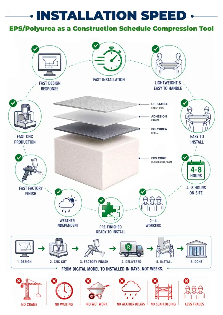
IN COMMERCIAL CONSTRUCTION, SCHEDULE COMPRESSION IS A DIRECT REVENUE STRATEGY
Every day of accelerated project delivery reduces financing carrying costs, advances the revenue start date for the completed asset, and reduces general conditions expenditure — site supervision, temporary facilities, and overhead.
Facade element installation is frequently a schedule-critical activity: it gates exterior envelope closure, painting, and final inspections.
The material system selected for architectural products therefore has a direct and quantifiable impact on project economics, not just on installed appearance.
OUR COMPANY PREFABRICATED PRODUCTS ARRIVE ON SITE FULLY PROCESSED: EPS-SHAPED, POLYUREA-COATED, PRIMED, AND FINISH-COATED
There is no formwork to build, no concrete to pour, no cure period to observe, no wet-trade sequencing to coordinate.
Fast-cure polyurea coating systems reduce factory finishing cycle time to hours per production run — a throughput rate that fiberglass laminating and wood finishing operations cannot match.
Installation Comparison:
- A typical installation of a complete product set requires a crew of 2–4 workers and 4–8 hours of on-site labor, versus multi-day or multi-week schedules for masonry piers, precast assemblies, or site-built wood elements.
- The dry-installation method eliminates weather-dependent cure windows that routinely extend wet-trade schedules in high-humidity and rain-prone environments.
CNC FABRICATION PROVIDES AN ADDITIONAL SCHEDULE ADVANTAGE AT THE DESIGN STAGE
Custom profile geometry is produced by modifying a digital model and initiating a milling run — a process measured in hours, not the weeks required to fabricate new fiberglass molds or commission custom extrusion tooling.
When design changes occur late in the project timeline, Royal Foam can respond without a schedule penalty.
Logistics & ROI:
Prefabrication also reduces site congestion: fewer trades, less equipment, and a compressed installation window mean that other parallel activities on the critical path are not disrupted.
Clients receive a measurable construction schedule advantage, a documented reduction in general conditions cost during facade installation, and earlier building turnover — all direct contributions to project-level return on investment.
Customization
| Factor | Description | Value | Unit | Standard/Code | Impact | Application | Notes |
|---|---|---|---|---|---|---|---|
| Diameter Options | Round/square/tapered sizing flexibility | 10–36+ | in | Project drawings | Supports many styles | All elements | Custom sizes possible |
| Height Options | Custom overall height capability | 8–24 | ft | Project drawings | Allows project-specific proportioning | Entries/porticos | Segmented builds for taller elements |
| Elements Styles | Doric, Ionic, Corinthian, Tuscan, custom | Custom | style | Architectural intent | Expands design appeal | Classical/custom work | Major differentiator |
| Elements Styles | Multiple elements profiles | Custom | style | Architectural intent | Supports architectural fit | All elements | Can match existing conditions |
| Elements Geometry | Round, square, fluted, tapered, smooth | Custom | geometry | Design drawings | Wide spec range | Commercial/residential | CNC-enabled |
| Texture Options | Smooth, stone, faux finishes | Custom | finish | Project spec | Improves design flexibility | Premium façades | Depends on finish system |
| Color Options | Painted to project palette | Custom | color | Paint spec | Brand/architectural matching | All visible work | Color affects maintenance cycle |
| Split / Wrap Options | Elements can be made as wraps around existing posts | Available | configuration | Manufacturing capability | Great for retrofit | Renovation work | Strong practical value |
| Multi-Part Fabrication | Large elements built in sections | Available | method | Manufacturing method | Makes shipping/install practical | Oversized elements | Joint detailing matters |
| Matching Existing Architecture | Custom profiles from photos/drawings | Available | service | Design workflow | High-value service for restoration | Historic/custom homes | Premium offering |
| Integrated Decorative Bands | Add rings, reveals, trim features | Custom | feature | Design drawings | Boosts visual distinction | Luxury/commercial | Good upsell |
| Specification Flexibility | Can tailor density, coat, finish, attachment | Project-specific | package | Project requirements | Lets product match use case | B2B specifications | Important for architects |
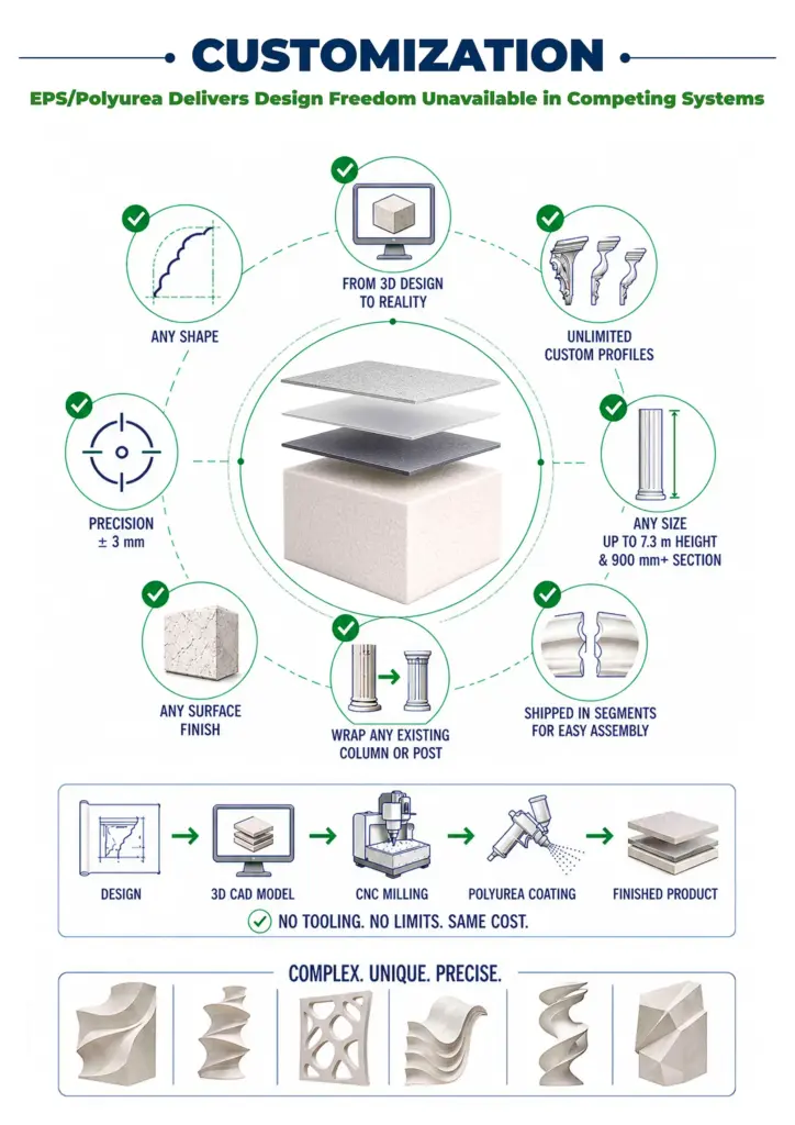
CUSTOMIZATION IS BUILT INTO THE PROCESS
Architectural customization is not a feature added to the EPS/polyurea production process — it is inherent to the CNC milling technology on which the process is elements.
A CNC mill operates from a three-dimensional digital model and reproduces any geometry the model defines, at the same per-unit cost regardless of profile complexity.
Manufacturing Advantages:
- No tooling penalty for unique geometry.
- No minimum run size for custom profiles.
- No dimensional constraint imposed by the manufacturing process itself.
WIDE GEOMETRIC AND SURFACE CAPABILITIES PRECISION REPRODUCTION
The practical range of geometric parameters is extensive.
Architectural orders — Doric, Ionic, Corinthian, Tuscan, and composite — are reproduced from measured drawings or high-resolution reference photography to profile tolerances of ±3 mm.
Contemporary and proprietary profiles developed by the project architect are produced directly from CAD files without intermediate tooling.
Dimensional Range:
Dimensional range extends from slender decorative elements to large-scale architectural components exceeding 900 mm in cross-section and 7.3 m in height, fabricated in interlocking segments for shipping and field assembly.
Surface Treatments
Surface treatments include:
- Smooth paint-ready finishes.
- Faux stone textures.
- Custom tactile profiles.
- Applied decorative bands.
All achievable within the same production system.
Renovation and Wrap Applications
The wrap configuration — EPS/polyurea cladding fabricated to enclose an existing structural post or elements — extends the application of Royal Foam products to renovation and restoration work where structural elements are already in place.
This single capability addresses a major gap in the competing product range: Fiberglass and PVC do not offer field-adaptable wrap systems.
Wood wraps are limited by available lumber dimensions and remain vulnerable to the same decay mechanisms as solid wood elements.
Direct Competitive Comparison
Custom fiberglass profiles require mold fabrication at $2,000–
15,000 per profile with 3–8 week lead times.
Custom PVC requires extrusion die investment with comparable cost and timeline.
Custom stone or wood millwork involves manual production at hourly craft rates with high variability.
Our company custom product is priced and scheduled on the same basis as standard product.
Final Client Benefit
Clients receive architectural elements that precisely match the design specification:
- No dimensional compromise.
- No design simplification.
- No cost penalty for doing the project right.
Engineering
| Factor | Description | Value | Unit | Standard/Code | Impact | Application | Notes |
|---|---|---|---|---|---|---|---|
| EPS Density Selection | Engineering starts with correct foam density | 1.0 / 2.0 | lb/ft³ | ASTM C578 | Affects compression and handling | All elements | Specify by use case |
| Wind Load Design | Exterior performance target | 120–180 | PSF | Florida Building Code | Critical engineering driver | Florida elements | Depends on exposure + anchorage |
| Polyurea Thickness | Protective shell design range | 30–60 | mil | Manufacturer spec | Major role in surface performance | Exterior elements | Royal Foam Working Range |
| Compressive Strength | Density-dependent EPS resistance | Approx. 10–25 | psi | ASTM C578 | Useful baseline for core behavior | All elements | Higher density generally stronger |
| Attachment Design | Anchorage must transfer real loads | Project-specific | detail | Engineer of record | Most important structural detail | Exterior installs | Substrate governs solution |
| Substrate Review | CMU, wood, steel, concrete behave differently | Required | status | Engineering practice | Controls fastener design | Retrofit/new | Always verify field conditions |
| Joint Engineering | Section seams need bonding + sealing | Required | status | Installation best practice | Affects long-term integrity | Tall/segmented elements | Do not treat as cosmetic only |
| Tolerance Control | Shop precision improves fit and appearance | ±1/8 typical | in | QC practice | Reduces rework | Custom elements | Important for wrap installs |
| CAD / CNC Workflow | Digital production supports repeatability | Yes | capability | Manufacturing workflow | Higher accuracy and customization | All custom work | A major differentiator |
| Detailing Package | Shop drawings/sections/install details | Available | service | Project workflow | Speeds approvals + install | B2B projects | Valuable for architects/GCs |
| Value Engineering | System can be optimized by density/coat/detail | Available | service | Engineering workflow | Improves budget-performance balance | Commercial projects | Strong sales tool |
| Field Coordination | Engineering must match actual site conditions | Required | status | Construction practice | Prevents failures and delays | Every project | Never skip verification |
Documentability as the Core Engineering Criterion
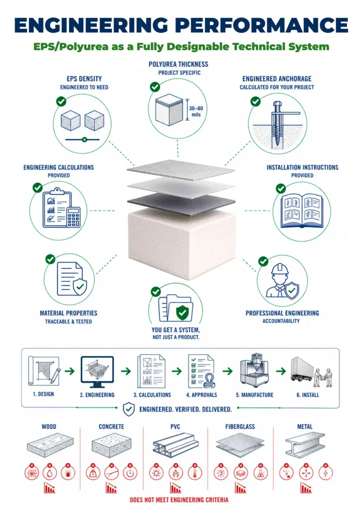
The defining criterion for material selection in engineered construction is documentability: the ability to assign specific, defensible numerical values to material properties, use those values in structural calculations, and have the resulting design reviewed and approved by a licensed engineer and the Authority Having Jurisdiction.
Why Competing Materials Fall Short
- WOOD: Wood fails this criterion for decorative architectural elements because its properties vary by species, moisture content, grain orientation, and defect distribution. Reference standards such as the NDS provide design value ranges, not precise values.
- FIBERGLASS: Custom fiberglass often fails because the fabricator cannot provide certified laminate property data for third-party engineering review.
- PVC: PVC is classified as a non-structural thermoplastic and is not used in engineered resistance calculations for wind or gravity loads.
EPS/polyurea is the only system in this competitive set that can be fully characterized, parameterically adjusted, and submitted to engineering review with complete material documentation.
PARAMETER-BASED ENGINEERING DESIGN
Our company system is engineered by parameter selection, not by default.
EPS Core Selection:
- Type I: 1.0 lb/ft³, compressive resistance approximately 10 psi per ASTM C578.
- Type II: 2.0 lb/ft³, compressive resistance approximately 25 psi.
Selection is based on service load requirements, exposure conditions, and substrate configuration.
POLYUREA SPECIFICATION
Polyurea coating thickness is specified in the range of 30–60 mils based on:
Impact exposure
- Moisture risk classification.
- Durability requirements for the specific installation.
- Anchorage Engineering.
Anchorage Engineering
Anchorage design is produced by the engineer of record, with fastener type, spacing, and embedment depth calculated for wind pressures of 120–180 PSF per the Florida Building Code, accounting for: CMU, Wood framing, Structural steel, Cast concrete, Element geometry, and Digital Accuracy.
CAD/CNC digital workflow ensures that fabricated geometry matches the engineered drawings to ±3 mm tolerance across every unit in the production run.
COMPLETE DOCUMENTATION PACKAGE
Our company technical documentation package includes:
- Shop drawings with all anchorage details and section cuts.
- Complete material specification with ASTM standard references for every component.
- Engineering calculations stamped by a Florida-licensed professional engineer when required.
- Installation guidelines coordinated with AHJ submittal requirements.
CLIENT AND APPROVAL BENEFITS
This package allows a structural engineer of record to defend the installation to any reviewing authority, and allows the owner to verify that the installed system performs to its calculated wind resistance rating specification.
Clients do not receive a product — they receive a fully engineered system with documented design basis, traceable material properties, and professional engineering accountability at every level of the specification.
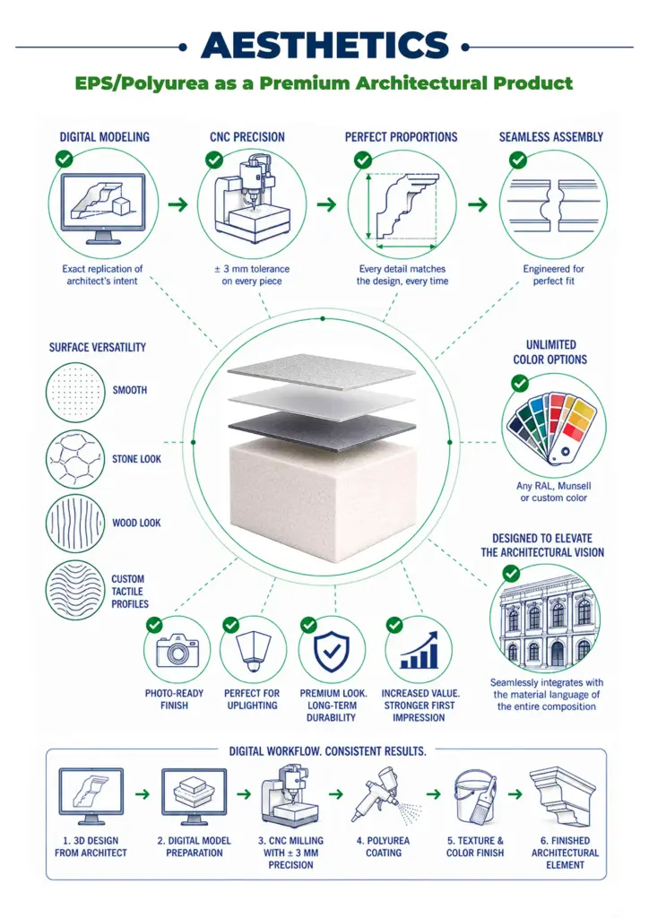
Aesthetics
| Factor | Description | Value | Unit | Standard/Code | Impact | Application | Notes |
|---|---|---|---|---|---|---|---|
| EPS Density | Core density affects dent resistance | 1.0 / 2.0 | b/ft³ | ASTM C578 | Higher density improves robustness | All elements | 2.0 better where abuse is higher |
| Polyurea Thickness | Primary hard coat thickness | 30–60 | mil | Manufacturer spec | Major durability driver | Exterior elements | Royal Foam Working Range |
| Water Absorption | EPS water absorption | Low | qualitative | ASTM C272 | Helps in humid environments | Exterior/interior | System still needs sealed finish |
| Moisture Resistance | Coated system resists rain splash | High | rating | Finish system | Florida suitability | Exterior elements | Seams must be sealed |
| UV Exposure | Finish must resist sun degradation | Requires topcoat | system | Paint spec | Affects color life | Exterior in Florida | Polyurea should be topcoated |
| Impact Resistance | Coating helps resist minor impact | Medium to high | rating | Coating spec | Important at pedestrian level | Retail/commercial | Not equivalent to solid concrete |
| Crack Control | Joint detailing reduces cracking risk | Project-specific | detail | Installation best practice | Preserves appearance | Segmented builds | Movement joints may be needed |
| Abrasion Resistance | Hard shell resists scuffing | High | rating | Coating spec | Useful in touch-prone areas | Entry elements | Depends on finish quality |
| Biological Resistance | EPS does not rot like wood | High | rating | Material property | Lowers maintenance | Exterior/interior | Still protect finish required |
| Corrosion Resistance | Foam shell will not rust | High | rating | Material property | Advantage over unprotected steel skins | Humid/coastal areas | Anchors may still require protection |
| Maintenance Cycle | Repaint/reseal as needed | 5–10 typical | years | Paint maintenance | Extends service life | Exterior projects | Climate + color affect cycle |
| Service Life | Expected full-system life | 15–25+ | years | Industry practice | Supports lifecycle value | All elements | Assumes proper installation |
Aesthetics as an Economic Variable
Architectural aesthetics function as a measurable economic variable. Studies of the U.S. commercial and residential real estate market consistently demonstrate that high-quality facade detailing:
- Increases perceived property value by 5–15%.
- Reduces time-on-market for sale or lease transactions.
For developers and property owners, the selection of architectural products that deliver premium visual quality is not a design preference — it is a elements allocation decision with a calculable return.
Our company products are specified for this reason by architects, developers, and restoration professionals who understand that facade quality is directly priced by the market.
PRECISION ARCHITECTURAL REPRODUCTION
Our company architectural products reproduce classical and contemporary architectural language at a level of precision that competing systems cannot achieve in production.
Geometry Quality
Capital and base projection geometry — the shadow-casting elements that establish architectural order and visual hierarchy — is milled to profile depths of 25–150 mm with edge sharpness and symmetry that extrusion, laminating, or handwork cannot consistently replicate at scale.
Surface Quality
The surface is delivered:
- Smooth.
- Pore-free.
- Free of process artifacts.
- No exposed glass fiber.
- No resin streaking.
- No tool marks.
- No grain telegraphing through the finish.
This surface quality is essential for:
- High-specular architectural paint systems.
- Professional photography of the completed building.
- Architectural uplighting.
All of which depend on a defect-free substrate to perform as designed.
Proportion and Design Consistency
Proportion control — the ratio of elements projection that defines architectural order — is maintained by digital model and CNC production, not by skilled tradesperson judgment.
This means that every unit in a project, regardless of production sequence or crew, matches the architect’s specified proportions exactly.
Surface and Color Flexibility
Surface texture options extend from smooth through faux stone to fully custom tactile profiles, allowing the facade system to match the material language of the broader architectural composition.
Color specification is unlimited — any RAL, Munsell, or custom mixed topcoat can be applied to the polyurea shell, providing exact palette coordination with adjacent facade materials.
Final Market Benefit
Clients receive a finished architectural product that:
- Strengthens the developer’s brand identity.
- Supports premium pricing.
- Supports higher occupancy rates for the completed asset.
Delivers long-term visual impact that does not degrade with age under normal service and maintenance conditions.
General Information
CSI Master Format Section 06 60 00 — Plastic Fabrications / Architectural Foam Systems
Unless specifically engineered and documented by a licensed structural engineer, decorative products specified in this section are non-structural architectural elements and shall not be considered primary load-bearing components.
This section specifies requirements for custom fabricated architectural foam systems manufactured by our company, Jacksonville, Florida.
Products are designed for:
- Commercial construction
- Institutional construction
- Hospitality construction
- Retail construction
- Residential construction
All systems consist of:
- Engineered foam cores — Expanded Polystyrene (EPS), Polyurethane (PU/PIR), or hybrid composite configurations
- High-performance polyurea elastomer protective coatings
- Exterior architectural finish systems
| Component | Description | Value | Unit |
|---|---|---|---|
| EPS Core | Primary shaped body | 1.0 / 2.0 | lb/ft³ |
| Adhesive Layer | Laminates foam sections | Construction-grade | system |
| Polyurea Shell | Primary hard protective coat | 30–60 | mil |
| Base Primer | Promotes coating bond | 1 coat | layer |
| Finish Coat | Paint or decorative finish | 2 coats | layer |
| Products | Top architectural element | Custom | dimension |
| Products | Main cylindrical/tapered body | Custom | dimension |
Design of all architectural foam systems specified herein is based on products manufactured and engineered by our company, Jacksonville, Florida, USA.
Our company operates as:
- An engineering-driven manufacturing platform
- Over 25 years of experience
- 10,000+ completed projects
In-house capability for:
- Structural design
- CNC fabrication
- Polyurea coating
- Full project lifecycle support
| Category | Details |
|---|---|
| Manufacturer | Decorative Architectural Shapes |
| Headquarters |
4225 James E Casey Dr, Unit #5 Westside Industrial Park, Jacksonville, FL 32219 |
| Engineering Experience | 25+ years / 10,000+ projects |
| Production Capability | CNC hot-wire EPS cutting, precision 3D routing, high-pressure polyurea spray systems |
| Market Served | Commercial, institutional, hospitality, retail, residential — nationwide B2B |
| Delivery Capability | Nationwide; typical lead time 7–14 business days |
 Lightweight
Up to 90% lighter than stone or precast concrete
 Impact Resistance
Mechanical impact · surface abrasion · installation damage
 Weather Resistance
Moisture · freeze-thaw · UV
degradation · thermal
 Long-term Durability
Structural integrity under exterior
commercial conditions
 Coastal Compatible
High humidity · salt exposure · elevated UV radiation
- 03 30 00 Cast-in-Place Concrete — substrate and support structures
- 05 12 00 Structural Steel Framing — internal armatures for large-scale elements
- 06 10 00 Rough Carpentry — wood nailers, blocking, backing substrates
- 07 21 00 Thermal Insulation — coordinate where foam serves dual thermal/ architectural function
- 07 24 00 Exterior Insulation & Finish Systems (EIFS) — coordinate with façade panel systems
- 07 92 00 Joint Sealants — perimeter and joint sealing at architectural foam elements
- 09 24 00 Portland Cement Stucco — alternate finish coat over polyurea base
- 09 90 00 Painting and Coating Systems — finish coat color matching
- 10 14 00 Signage — coordinate with monument sign and 3D branding elements
- 12 36 00 Countertops — coordinate where custom foam elements integrate with millwork
- ASTM C578 Standard Specification for Rigid, Cellular Polystyrene Thermal Insulation — Types I through XV
- ASTM D6817 Standard Specification for Rigid Cellular Polystyrene Geofoam
- ASTM C591 Standard Specification for Unfaced Preformed Rigid Cellular Polyisocyanurate Thermal Insulation
- ASTM C1029 Standard Specification for Spray-Applied Rigid Cellular Polyurethane Thermal Insulation
- ASTM D1621 Standard Test Method for Compressive Properties of Rigid Cellular Plastics
- ASTM D1623 Standard Test Method for Tensile and Tensile Adhesion Properties of Rigid Cellular Plastics
- ASTM C273 Standard Test Method for Shear Properties of Sandwich Core Materials
- ASTM D412 Standard Test Methods for Vulcanized Rubber and Thermoplastic Elastomers — Tension
- ASTM D2240 Standard Test Method for Rubber Property — Durometer Hardness
- ASTM D4541 Standard Test Method for Pull-Off Strength of Coatings
- ASTM D4065 Standard Practice for Plastics — Classification — Application of Polyurea Coating Systems
- ASTM E84 Standard Test Method for Surface Burning Characteristics of Building Materials (Tunnel Test)
- ASTM E90 Standard Test Method for Laboratory Measurement of Airborne Sound Attenuation of Building Partitions
- ASTM C423 Standard Test Method for Sound Absorption and Sound Absorption Coefficients
- ASTM G154 Standard Practice for Operating Fluorescent Ultraviolet (UV) Lamp Apparatus for Exposure of Nonmetallic Materials
- ASTM C518 Standard Test Method for Steady-State Thermal Transmission Properties by Means of the Heat Flow Meter Apparatus
- ASCE 7-22 Minimum Design Loads and Associated Criteria for Buildings and Other Structures
- IBC 2021 International Building Code — Section 2603: Foam Plastic Insulation
- IFC 2021 International Fire Code
- ICC-ES AC71 Acceptance Criteria for Foam Plastic Insulation in Continuous Insulation Applications
- NFPA 101 Life Safety Code
- FM 4474 Approval Standard for Evaluating the Simulated Wind Uplift Resistance of Roof Assemblies
- CSI Master Format 2016 Edition — Division 06 Wood, Plastics, and Composites
Structural Performance
All architectural foam systems shall be designed and fabricated to withstand applicable structural loads including:
- Self-weight
- Installation loads
- Wind-induced pressures
- Impact loads appropriate to the application and occupancy
Systems required to resist wind loads shall comply with ASCE 7-22 for the design wind speed and exposure category of the project site.
Structural calculations shall be prepared by a licensed Professional Engineer where required by the Authority Having Jurisdiction (AHJ).
Wind Load Resistance
Exterior architectural elements shall be designed for component and cladding (C&C) wind pressures per ASCE 7-22 Chapter 30.
Attachment systems, fastener schedules, and foam core shear/compressive strength shall be verified against design wind pressures with a minimum safety factor of 3.0 per ICC-ES AC71.
FM-rated assemblies shall be provided where required by insurer or AHJ.
Refer to Part 4 — Wind Load Reference Data.
Thermal Performance
Where foam elements serve a thermal insulation function, R-values shall comply with the energy code requirements of the applicable jurisdiction.
- EPS Type II (1.35 pcf) provides R-4.17 per inch
- EPS Type IX (1.80 pcf) provides R-4.35 per inch
- PU closed-cell systems provide R-6.0 to R-6.5 per inch per ASTM C518 at 75°F
Thermal Performance
Polyurea protective coating system shall provide a continuous waterproof membrane over all exposed foam surfaces.
Coating system shall resist:
- Moisture penetration
- Freeze-thaw cycling
- UV degradation
Water vapor permeance of coating system shall be compatible with wall assembly vapor control requirements.
Coastal and high-humidity installations shall specify enhanced UV-stable exterior finish coatings.
Acoustic Performance
Where acoustic separation or sound control is required, foam systems shall be specified in conjunction with appropriate wall/floor/ceiling assemblies.
- Open-cell polyurethane spray foam provides NRC 0.70–0.95 at 2″–4″ thickness
- For assemblies required to achieve STC 50 per IBC Section 1207, foam fill shall be used in conjunction with appropriate framing, gypsum wallboard, and resilient channel systems
Refer to Part 4 — Acoustic Performance Data.
Dimensional Stability
Foam core materials shall maintain dimensional stability under the full range of service temperatures anticipated at the project location.
- EPS materials shall comply with ASTM C578 requirements for dimensional stability
- Polyurea coating system shall accommodate thermal expansion and contraction without cracking, delamination, or loss of adhesion over the service life of the installation
Impact & Abrasion Resistance
Polyurea coating system shall provide:
- Shore D hardness ≥ 55 per ASTM D2240
- Tensile strength of coating ≥ 2,500 psi per ASTM D412
- Elongation at break ≥ 200% per ASTM D412
- Adhesion to EPS substrate ≥ 250 psi pull-off strength per ASTM D4541
UV Stability
Exterior finish coating systems shall be UV-stable and shall not exhibit:
- Significant color shift
- Chalking
- Loss of gloss under accelerated UV weathering per ASTM G154.
All foam materials shall be protected from direct UV exposure within 30 days of installation by application of appropriate finish coatings or cladding systems.
Weight Efficiency
Architectural foam systems shall provide weight reduction of up to 90 percent compared to equivalent stone, precast concrete, or cast stone elements, thereby reducing structural dead loads and facilitating accelerated installation.
Product Data
Manufacturer technical documentation including material composition, density range, fabrication process description, coating system data sheets, and installation guidelines.
Include ASTM test reports for EPS (C578), polyurea coating (D412, D2240, D4541, E84), and thermal performance (C518) as applicable.
Shop Drawings
Project-specific shop drawings for each custom element.
Include plan, elevation, and section views with all dimensions; connection and attachment details; internal armature or mounting hardware; joint locations and configurations; and installation sequence.
Engineering Calculations
Where required by project specifications or AHJ: structural calculations by licensed PE verifying foam core adequacy, attachment capacity, and wind load resistance.
Include design wind speed, exposure category, and C&C pressure calculations per ASCE 7-22.
Astm E84 Test Reports
Current ASTM E84 flame spread and smoke developed test reports for foam and coating system as installed, at the thickness and density specified.
Samples
Finish coating samples on minimum 6″ x 6″ EPS substrate, illustrating texture, color, and sheen level. Provide color range samples where multiple finish options are offered.
Warranty Documentation
Executed warranty document per Section 1.10 prior to Substantial Completion.
Manufacturer shall be a firm with not less than 10 years of continuous experience fabricating custom architectural foam elements for commercial construction projects. Manufacturer shall demonstrate the following in-house capabilities:
- CNC hot-wire EPS cutting systems capable of producing complex three-dimensional profiles.
- Precision multi-axis CNC routing and profiling equipment.
- High-pressure plural-component polyurea spray coating systems.
- In-house structural design and CAD/3D modeling capability.
- Direct collaboration capability with project architects, engineers, and contractors.
- Quality management system with documented inspection procedures at each production stage.
- Capability to provide design modifications during production without schedule impact.
- Pre-assembled delivery systems reducing field installation cost and time.
8 Delivery, Storage & Handling
- Deliver products in manufacturer’s packaging with identification labels intact. Inspect upon delivery and document any damage before accepting shipment.
- Store foam elements in a dry, sheltered location protected from precipitation, direct sunlight, and temperatures below -20°F or above 140°F. Store flat on clean, level supports. Do not stack elements in a manner that causes deformation or surface damage.
- Free product storage at our manufacturing facility is available for clients not yet ready for installation — contact us for terms.
- Handle elements with clean gloves or padding to prevent surface damage to finish coatings. Do not drag elements on abrasive surfaces.
Decorative Architectural Shapes warrants that products furnished under this section shall be free from defects in:
- materials
- fabrication
for a period of:
- 5 years from the date of Substantial Completion for standard systems
- 10 years for enhanced coating systems
against delamination of polyurea coating from EPS substrate under normal service conditions.
Warranty Excludes Damage From:
- improper installation
- vandalism
- impact beyond design parameters
- chemical exposure not specified
- UV degradation where finish coating is not maintained per manufacturer recommendations.
The preparers of this document make no representations or warranties, express or implied, as to the accuracy, completeness, currentness, or suitability of any information contained herein for any particular application.
Building codes, material requirements, allowable loads, fire safety classifications, acoustic performance standards, and wind load provisions vary significantly by:
- state,
- county,
- municipality,
- and local jurisdiction,
and are subject to change with adoption of new code editions or local amendments.
This document does not constitute:
- an engineering report,
- professional design document,
- certified test report,
- code compliance determination,
- or legally binding specification of any kind.
The preparers, authors, and distributors of this document expressly disclaim any and all liability for any loss, damage, claim, or expense — direct, indirect, incidental, or consequential — arising from the use of or reliance on any information contained herein.
Products
EPS core material shall comply with ASTM C578. Select density type based on design loads, coating system, and project performance requirements.
| ASTM Type | Nom. Density (lb/ft³) | Compressive Str. 10% (psi) | Flexural Str. (psi) | Shear Str. (psi) | R-value/ inch | Typical Application |
|---|---|---|---|---|---|---|
| Type I (EPS15) | 0.90–1.14 | 10–14 | 25–30 | 18–22 | 3.85 | General decorative elements, signage cores, interior applications |
| Type VIII (EPS19) | 1.15–1.34 | 13–18 | 30–38 | 23–25 | 3.92 | Moderate-load decorative elements, exterior columns ≤30 ft |
| Type II (EPS22) | 1.35–1.79 | 15–21 | 40–50 | 26–32 | 4.17 | Standard exterior architectural elements, SIP cores, façade panels |
| Type IX (EPS29) | 1.80–2.20 | 25–33 | 50–75 | 33–37 | 4.35 | High-load columns, roofing elements, wind zone 3+ applications |
| Type XIV (EPS39) | 2.40–2.80 | 35–50 | 60–90 | 40–48 | 4.50 | Heavy structural panels, bridge deck formwork, extreme wind zones |
| Type XV (EPS46) | 2.80–3.50 | 50–75 | 75–110 | 48–60 | 4.60 | Maximum structural demand; SIP cores for hurricane-rated assemblies |
| Type / Standard | Density (lb/ft³) | Cell Type | Compressive Str. 10% (psi) | R-value/ inch | Primary Use |
|---|---|---|---|---|---|
| PU Open-cell SPF (ASTM C1029 Type I) | 0.4–0.6 | Open | 0.1–0.5 | 3.7 | Cavity fill, air sealing, acoustic absorption (NRC 0.70–0.95) |
| PU Closed-cell SPF (ASTM C1029 Type II) | 1.5–2.0 | Closed | 20–35 | 6.2 | Continuous insulation, air/vapor barrier, structural cavity fill |
| Rigid PU/PIR (ASTM C591 Type II) | 2.5 | Closed | 35 | 6.1 | High-R ci panels, roof insulation, structural panels |
| Rigid PU/PIR (ASTM C591 Type III) | 3.0 | Closed | 45 | 6.3 | High-load ci, commercial roofing, hurricane-zone applications |
| HD Rigid PU (ASTM C591 Type VI) | 6.0 | Closed | 125 | 5.8 | Industrial, cold storage, maximum structural demand |
Polyurea protective coating shall be a 100% solids, two-component, aromatic or aliphatic polyurea elastomer system applied by high-pressure, heated plural-component spray quipment. Coating shall be applied to all exposed EPS or PU foam surfaces prior to application of architectural finish coats..
| Property | Test Method | Requirement | Unit |
|---|---|---|---|
| Coating Thickness — Standard | DFT gauge | 20–40 | mil |
| Coating Thickness — Heavy-duty | DFT gauge | 60–120 | mil |
| Tensile Strength (min.) | ASTM D412 | ≥ 2,500 | psi |
| Elongation at Break (min.) | ASTM D412 | ≥ 200 | % |
| Shore D Hardness | ASTM D2240 | 55–75 | — |
| Adhesion to EPS — Pull-off (min.) | ASTM D4541 | ≥ 250 | psi |
| Flame Spread Index (max.) | ASTM E84 | ≤ 25 | — |
| Smoke Developed Index (max.) | ASTM E84 | ≤ 450 | — |
| UV Weathering Resistance | ASTM G154 | Pass — 1,000 hr min | — |
| Water Absorption (max.) | ASTM D570 | ≤ 1 | % by weight |
| Service Temperature Range | — | -40 to +200 | °F |
| Gel Time (fast system) | — | 3–7 | seconds |
| Tack-Free Time | — | < 30 | seconds |
Architectural Columns
- Types: Round, Square, Tapered (entasis), Classical Orders (Doric, Ionic, Corinthian, Tuscan, Composite)
- Diameter range: 4 inches to 60 inches; custom sizes available
- Height: up to 40 feet in sectional assembly; single-piece up to 14 feet
Core: EPS Type II minimum (Type IX recommended for exterior/coastal); PU/PIR available on request
Sections: single-piece or sectional with concealed staggered slip-joint connections
Bases and capitals: integrated or separate; classical profiles per architect’s drawings
Internal reinforcement: steel pipe armature available for structural continuity where required by PE
Finish: polyurea base coat + exterior architectural topcoat; smooth, textured, or custom profiles
Applications: porticos, colonnades, entryways, façade features, resort/hospitality, monument structures
Decorative Beams, Brackets & Corbels
Types: exposed ceiling beams, faux timber posts, wall brackets, structural-look corbels, rafter tails
Profiles: rectangular, tapered, hand-hewn texture, smooth architectural, custom cross-sections
Dimensions: custom per drawings; typical spans up to 20 feet in single piece
Core: EPS Type II or Type IX depending on exposed span and load requirements
Surface: textured polyurea replicating wood grain, stone, or custom architectural finish
Hollow or solid construction; hollow beams suitable for concealed electrical/mechanical routing
Mounting: internal blocking nailers or through-bolt attachment systems per structural requirements
Facade Panels & Cladding Systems
Types: flat insulated panels, profiled architectural panels, lap siding profiles, wainscot systems
Core: EPS Type II or Type IX; PU/PIR closed-cell for high-R applications
Panel size: custom to project; standard modules available; maximum CNC billet size 36″x48″x192″
Thermal performance: R-8 to R-30+ depending on core type and thickness
Surface: textured polyurea + exterior architectural finish; faux stone, brick, wood, or smooth
Attachment: mechanical fastener systems per ICC-ES AC71; adhesive-mechanical hybrid available
Wind load compliance: design per ASCE 7-22 with engineering calculations provided by Royal Foam
Cornices, Moldings, Trim & Surrounds
Types: crown molding, bed molding, band molding, window surrounds, door surrounds, keystones
Profile library: classical profiles plus full custom CNC-profiled geometry per architect’s drawings
Core: EPS Type I minimum; Type II recommended for exterior applications
Typical thickness range: 1 inch to 12 inches projection; lengths to 20 feet
Joints: mitered, scarfed, or overlapping; sealed with compatible flexible sealant
Finish: smooth painted, textured stucco-look, stone-replicated, or custom architectural coatings
Compatibility with EIFS, stucco, painted wood, and standard exterior finish systems
Monument Signs & 3D Branding Structures
Types: freestanding monument signs, dimensional lettering, 3D logo structures, entry pylons
Core: EPS or PU/PIR depending on structural requirements and exposure conditions
Dimensional lettering: any font, any size; maximum practical height 8 feet per letter
Sign cabinet depth: custom from 2 inches to 36 inches relief
Surface: polyurea base + paint/coating for weather resistance; illumination cutouts available
Internal steel armature and base plate anchor systems per structural engineer’s drawings
Applications: retail, hospitality, real estate, institutional, municipal entry features
Faux Material Systems
Faux Wood: EPS or PU core with hand-textured polyurea replicating cedar, oak, pine, weathered timber
Faux Stone: irregular profiles replicating limestone, fieldstone, sandstone, cut stone
Faux Brick: modular panel or individual unit profiles; mortar joint detail available
Faux Concrete: board-formed, broom-finished, or smooth architectural concrete texture
Color: integral pigmented topcoats; multi-tone hand-stained finishes available
Performance: fully waterproof; significantly lighter than real material counterparts
Applications: interior accent walls, exterior feature walls, retail/hospitality environments
Custom Sculptural & Artistic Elements
Capability: fully custom three-dimensional forms from digital files (STL, OBJ, DXF)
Typical projects: themed environments, retail experiential installations, large-scale sculptures
Core: EPS Type II or higher; PU/PIR for complex thin-wall geometries
Maximum single-piece dimensions: 36″ x 48″ x 192″ (billet); larger elements sectional assembly
Digital-to-physical workflow: client supplies 3D model; Royal Foam engineers toolpath and produces
Finish: polyurea + custom coating matching any architectural or brand color specification
Structural Insulated Panel (Sip) Cores
Core materials: EPS Type II, Type IX, or PU/PIR closed-cell per structural requirements
Core thickness: 3.5 to 12.25 inches standard; custom thicknesses available
Core R-values: EPS R-14 to R-50+; PU/PIR R-21 to R-80+ depending on thickness and type
Facings: OSB, plywood, steel, aluminum, fiber cement, or custom facings bonded by others
Dimensional tolerance: ±1/8″ per 10 feet per ASTM C578 dimensional stability requirements
Applications: wall panels, roof panels, floor panels, cold storage construction
Engineering: structural calculations for SIP assemblies available from Royal Foam engineering
Execution
1 Examination
- Verify that supporting structures, substrates, and mounting surfaces are plumb, level, and aligned within tolerances required for product installation.
- Confirm that substrates are structurally adequate to receive design attachment loads including dead load of foam elements and design wind pressures.
- Verify that rough openings, blocking, nailers, and embedded anchors are properly positioned per approved shop drawings before beginning installation.
- Do not proceed with installation until unsatisfactory conditions are corrected. Report discrepancies to Architect before proceeding.
2 Preparation
- Clean all mounting surfaces of dust, oil, form release, and debris that could impair adhesive bond or fastener engagement.
- Install any required blocking, shims, or leveling plates. Protect adjacent finish surfaces from adhesive, sealant, and coating overspray.
- Prime surfaces where required by adhesive or coating manufacturer.
3 Installation — General
- Install all elements per manufacturer’s written installation instructions and approved shop drawings.
- Maintain plumb and level tolerances of ±1/8″ per 10 feet of height.
- Assemble sectional elements using manufacturer -recommended adhesives and concealed mechanical fasteners. Stagger joints a minimum of 12 inches from adjacent section joints.
- Install internal armatures and mounting hardware before applying outer elements. Conceal all structural hardware within finished elements.
- Apply compatible flexible sealant at all joints between architectural foam elements and adjacent construction. Tool joints to produce smooth, consistent bead.
- Apply touch-up finish coatings to match factory -applied coatings at field cuts, joints, and any areas of installation damage. Match color, texture, and sheen.
- Do not install foam elements within 3 inches of heat-emitting devices, chimneys, or unprotected luminaires without thermal protection per IBC 2603
4 Installation — Columns Specific
- Set column base on pre-leveled bearing surface. Align base to column centerline marked on substrate. Secure base with anchor bolts or adhesive per shop drawings.
- Install column shaft sections from base upward. Check plumb in two directions at each section. Apply adhesive at mating surfaces before joining.
- Install capital with adhesive and concealed fasteners. Align capital to column axis.
- At sectional assemblies exceeding 16 feet height, verify that internal armature continuity is maintained through all sections before applying outer foam elements.
5 Field Quality Control
- Inspect installed elements for plumb, level, and alignment per tolerances specified.
- Verify coating continuity at all joints, penetrations, and field-cut surfaces.
- Confirm sealant joints are fully tooled with no voids or gaps.
- Document any deviations from approved shop drawings and obtain Architect acceptance before Substantial Completion.
6 Cleaning & Protection
- Remove construction debris, adhesive residue, and coating overspray from installed elements.
- Use only mild detergent and water for final cleaning. Do not use abrasive cleaners, solvents, or high-pressure washers that may damage protective coatings.
- Protect installed elements from construction traffic and subsequent trades until project Substantial Completion using temporary padding or protective coverings.
Technical Data
EPS Geofoam · R-Values · Polyurea Performance · Wind Load · Fire Safety · Acoustic
1 Eps Geofoam Data — Astm D6817 Properties
EPS Geofoam per ASTM D6817 — applicable for geotechnical, below-grade, and structural fill applications. Also reference basis for high-density EPS specified in structural architectural applications.
| Property | Units | EPS14 Type IX | EPS16 Type I | EPS19 Type VIII | EPS22 Type II | EPS39 Type XIV | EPS39 Type XIV | EPS46 Type XV |
|---|---|---|---|---|---|---|---|---|
| Min. Density | lb/ft³ | 0.70 | 0.90 | 1.15 | 1.35 | 1.80 | 2.40 | 2.85 |
| Min. Density | kg/m³ | 11 | 14 | 18 | 22 | 29 | 38 | 45 |
| Comp. Res. @10% def. | psi | 5.6 | 10.2 | 16.0 | 19.6 | 29.0 | 40.0 | 50.0 |
| Comp. Res. @1% def. | psi | 0.4 | 0.7 | 1.1 | 1.4 | 2.7 | 3.5 | 4.3 |
| Comp. Res. @5% def. | psi | 2.2 | 3.0 | 5.6 | 7.3 | 10.9 | 15.0 | 18.8 |
| Flexural Modulus | psi | 220 | 400 | 540 | 730 | 1010 | 1500 | 1900 |
| Flexural Str. (min.) | psi | 10 | 25.0 | 30.0 | 30.0 | 50.0 | 60.0 | 75.0 |
| Water Absorption (max.) | vol% | 4.0 | 4.0 | 3.0 | 3.0 | 2.5 | 2.0 | 2.0 |
| Oxygen Index (min.) | % | 24.0 | 24.0 | 24.0 | 24.0 | 24.0 | 24.0 | 24.0 |
| Buoyancy Force | lb/ft³ | 61.7 | 61.5 | 61.3 | 61.1 | 60.0 | 60.0 | 59.5 |
2 Eps & Pu Foam R-Values By Type & Thickness (Astm C518 75°F)
| Thickness (in) | EPS Type I 0.9 pcf | EPS Type II 1.35 pcf | EPS Type IX 1.80 pcf | PU Open-cell 0.5 lb | PU Closed-cell 2.0 lb | PU Rigid PIR 3.0 lb |
|---|---|---|---|---|---|---|
| 1″ | 3.9 | 4.2 | 4.3 | 3.7 | 6.2 | 6.3 |
| 1-1/2″ | 5.8 | 6.3 | 6.5 | 5.5 | 9.3 | 9.4 |
| 2″ | 7.7 | 8.3 | 8.7 | 7.4 | 12.4 | 12.6 |
| 3″ | 11.6 | 12.5 | 13.0 | 11.1 | 18.6 | 18.9 |
| 4″ | 15.4 | 16.7 | 17.4 | 14.8 | 24.8 | 25.2 |
| 5″ | 19.2 | 20.9 | 21.8 | 18.5 | 31.0 | 31.5 |
| 6″ | 23.1 | 25.0 | 26.1 | 22.2 | 37.2 | 37.8 |
| 8″ | 30.8 | 33.4 | 34.8 | 29.6 | 49.6 | 50.4 |
3 Fire Safety Data Summary — Astm E84 / Ibc 2603
| ASTM Type | Density (lb/ft³) | Compressive Str. (psi) | Allow. Roof Uplift (psf) | Max Wind Speed Exp C (mph) | IBC Reference |
|---|---|---|---|---|---|
| EPS Type I | 0.90 | 10–14 | 18–23 | 90–100 | 1-30 to 1-45 |
| EPS Type II | 1.35 | 15–21 | 27–35 | 110–120 | 1-60 to 1-75 |
| EPS Type IX | 1.80 | 25–33 | 33–45 | 120–135 | 1-75 to 1-90 |
| PU CC SPF 2.0 | 2.0 | 20–35 | 38–47 | 125–135 | 1-60 to 1-75 |
| PU Rigid 3.0 | 3.0 | 45 | 53–60 | 140–155 | 1-90 to 1-120 |
| PU HD 6.0 | 6.0 | 125 | 80–88 | 165–175 | 1-120 to 1-150+ |
Values based on ICC-ES AC71 methodology, SF = 3.0. Actual design pressures are site-specific and must be calculated by licensed PE using ASCE 7-22 for project location, risk category, and exposure.
4 Wind Load Quick Reference — Asce 7-22 / Icc-Es Ac71
| ASTM Type | Density (lb/ft³) | Compressive Str. (psi) | Allow. Roof Uplift (psf) | Max Wind Speed Exp C (mph) | IBC Reference |
|---|---|---|---|---|---|
| EPS Type I | 0.90 | 10–14 | 18–23 | 90–100 | 1-30 to 1-45 |
| EPS Type II | 1.35 | 15–21 | 27–35 | 110–120 | 1-60 to 1-75 |
| EPS Type IX | 1.80 | 25–33 | 33–45 | 120–135 | 1-75 to 1-90 |
| PU CC SPF 2.0 | 2.0 | 20–35 | 38–47 | 125–135 | 1-60 to 1-75 |
| PU Rigid 3.0 | 3.0 | 45 | 53–60 | 140–155 | 1-90 to 1-120 |
| PU HD 6.0 | 6.0 | 125 | 80–88 | 165–175 | 1-120 to 1-150+ |
Values based on ICC-ES AC71 methodology, SF = 3.0. Actual design pressures are site-specific and must be calculated by licensed PE using ASCE 7-22 for project location, risk category, and exposure.
Engineering & Compliance
Decorative Architectural Shapes Engineering Services · Code Compliance · Submittal Support
1 Decorative Architectural Shapes Engineering Services
Cad / 3D Modeling
Full 3D modeling and shop drawing production from architect’s design intent. DXF, DWG, STL, OBJ, and Revit file formats supported.
Wind Load Analysis
Site-specific ASCE 7-22 wind pressure calculations, exposure category determination, and component- and-cladding (C&C;) pressure tables for all project zones.
Installation Optimization
Pre-engineered installation sequences, assembly procedures, and logistics planning to minimize field labor and eliminate installation errors.
Value Engineering
Systematic review of project design to identify cost reduction opportunities through material ptimization, simplified geometry, or production sequencing without compromising architectural intent or performance.
Structural Design & Load Analysis
In-house structural analysis of foam element dead loads, attachment systems, and wind pressure capacity. PE-stamped calculations available for Risk Category III/IV projects or wind speeds exceeding 130 mph.
Custom Mounting System Design
Engineering of internal armatures, base onnections, through-bolt systems, and concealed attachment hardware optimized for each project’s structural conditions.
Submittal & Permitting Support
Preparation of AHJ submittals, product data packages, ASTM test reports, ICC-ES evaluation report references, and permit-ready documentation packages.
2 Code Compliance Matrix
| Code / Standard | Section | Requirement | Decorative Architectural Shapes Compliance Method |
|---|---|---|---|
| IBC 2021 | §2603.3 | FSI ≤ 25 or ≤ 75 per occupancy | ASTM E84 test reports provided for all foam/coating systems |
| IBC 2021 | §2603.4 | Thermal barrier on interior faces | Product data specifies TB requirement; field verification checklist provided |
| IBC 2021 | §2603.5 | NFPA 285 for exterior walls >1 story | FM-listed assemblies available; NFPA 285 test report references on request |
| ASCE 7-22 | §26–30 | Design wind pressures — C&C | Site-specific ASCE 7-22 calculations by PE on request |
| ICC-ES AC71 | §4–5 | Fastener schedule & foam strength | AC71-compliant fastener tables; PE calculations confirming SF ≥ 3.0 |
| ASTM C578 | Table 1 | EPS density & mechanical properties | Material certifications provided; lot testing on request |
| IBC 2021 | §1207 | STC 50 between dwelling units | Assembly data provided; spray foam + framing + GWB assemblies documented |
| ENERGY CODE | per state | Minimum R-value ci | R-value tables and energy code compliance data provided per project state |
| CSI MasterFormat | 06 60 00 | Plastic Fabrications specification | This document prepared in full CSI 3-Part Format compliance |
3 Why Decorative Architectural Shapes — Engineering Differentiators
| Capability | Decorative Architectural Shapes | Typical Competitor |
|---|---|---|
| Engineering in-house | YES — PE, structural, CAD, 3D | NO — outsourced or none |
| Design changes during production | YES — real-time adaptation | NO — new order required |
| Lead time | 7–14 business days typical | 4–8 weeks typical |
| Custom geometry capability | Unlimited — CNC from any 3D file | Limited standard profiles |
| Pre-assembled delivery | YES — reduces site labor | NO — field assembly required |
| Wind load calculations | YES — site-specific ASCE 7-22 | NO — generic data only |
| ASTM E84 documentation | YES — current test reports provided | Sometimes — may require extra cost |
| Coastal/hurricane zone experience | YES — FL-based, 25+ years | Limited |
| Free warehouse storage | YES — hold until client ready | NO |
| Nationwide delivery | YES — all 50 states | Regional only |
| TCO reduction vs stone/concrete | 30–50% documented savings | Not quantified |
Acoustic Metrics - Definitions & Applicable Standards
Definitions & Applicable Standards
| Metric | Full Name | Standard | What It Measures | Typical Range (Insulation) |
|---|---|---|---|---|
| STC | Sound Transmission Class | ASTM E413 / E90 | Airborne sound isolation between rooms (speech, music, TV). Higher = better isolation. | 25–65 (assemblies) |
| IIC | Impact Insulation Class | ASTM E413 / E492 | Structure-borne impact noise (footsteps, dropped objects). Higher = better isolation. | 25–70 (assemblies) |
| NRC | Noise Reduction Coefficient | ASTM C423 / ISO 354 | Average sound absorption across 250–2000 Hz (four-bandaverage). 0 = fully reflective, 1.0 = fully absorptive. | 0.05–0.95 |
| SAC | Sound Absorption Coefficient | ASTM C423 | Absorption at each 1/3-octave frequency band. Used for room acoustics design. | 0.01–1.00 per band |
| OITC | Outdoor-Indoor Transmission Class | ASTM E1332 | Similar to STC but weighted for low-frequency exterior noise (traffic, aircraft). | 20–55 (assemblies) |
| Delta IIC | Impact Isolation Improvement | ISO 140-8 | Improvement in IIC provided by floor underlayment over bare concrete or wood sub-floor. | +3 to +30 dB |
Code Minimum Acoustic Requirements
| Code / Standard | Section | Requirement | Applies To |
|---|---|---|---|
| IBC 2021 | Section 1207 | STC ≥ 50 (field-tested FIIC/FSTC) between dwelling units | Multi-family residential, hotels, motels, dormitories |
| IRC 2021 | Section R302.13 | STC ≥ 45 (lab) / FSTC ≥ 45 (field) for walls/floors between units | Two-family dwellings, townhouses |
| IRC 2021 | Section R302.13 | IIC ≥ 50 (lab) / FIIC ≥ 45 (field) for floor/ceiling assemblies | Two-family dwellings, townhouses |
| FHA / HUD | Noise Guidebook | Interior DNL ≤ 45 dB; STC ≥ 25 for units near highways/airports | Federally-assisted housing |
| OSHA 29 CFR 1910.95 | — | Max 85 dBA 8-hr TWA; engineering controls required before PPE | Occupational / industrial noise |
| ASHRAE 2019 HVAC Apps | Chapter 49 | NC 25–35 (bedrooms), NC 30–40 (offices), NC 40–50 (open offices) | HVAC system background noise — foam used as duct liner |
| IEC 61672 / ISO 1996 | — | Environmental noise measurement — foam used in measurement rooms | Acoustic testing facilities |
Section 1 — Expanded Polystyrene (Eps) Acoustic Performance | Astm C578
EPS is primarily a thermal insulation material. Its acoustic performance varies significantly by density and thickness. EPS is NOT a high-performance acoustic material in isolation — it must be used in composite assemblies to meet IBC STC/IIC minimums. EPS provides moderate sound absorption (NRC 0.10–0.35) and limited transmission loss.
Table 1a — Eps Sound Absorption Coefficient (Sac) By Density & Thickness (Astm C423 / Iso 354)
| ASTM Type | Density (lb/ft³) | Thickness | 125 Hz | 250 Hz | 500 Hz | 1000 Hz | 2000 Hz | 4000 Hz | NRC (avg) | Performance |
|---|---|---|---|---|---|---|---|---|---|---|
| Type I | 0.90–1.14 | 1″ | 0.02 | 0.03 | 0.05 | 0.06 | 0.07 | 0.07 | 0.05 | Poor |
| Type I | 0.90–1.14 | 2″ | 0.03 | 0.05 | 0.08 | 0.10 | 0.11 | 0.09 | 0.09 | Poor |
| Type I | 0.90–1.14 | 3″ | 0.05 | 0.07 | 0.10 | 0.13 | 0.13 | 0.10 | 0.11 | Poor |
| Type I | 0.90–1.14 | 4″ | 0.06 | 0.09 | 0.12 | 0.15 | 0.14 | 0.11 | 0.13 | Poor |
| Type VIII | 1.15–1.34 | 1″ | 0.02 | 0.04 | 0.06 | 0.07 | 0.08 | 0.08 | 0.06 | Poor |
| Type VIII | 1.15–1.34 | 2″ | 0.03 | 0.06 | 0.09 | 0.11 | 0.12 | 0.10 | 0.10 | Poor |
| Type VIII | 1.15–1.34 | 3″ | 0.05 | 0.08 | 0.11 | 0.14 | 0.14 | 0.11 | 0.12 | Poor |
| Type VIII | 1.15–1.34 | 4″ | 0.07 | 0.10 | 0.14 | 0.17 | 0.16 | 0.12 | 0.15 | Poor–Fair |
| Type II | 1.35–1.79 | 1″ | 0.03 | 0.04 | 0.07 | 0.08 | 0.09 | 0.08 | 0.07 | Poor |
| Type II | 1.35–1.79 | 2″ | 0.04 | 0.07 | 0.10 | 0.12 | 0.13 | 0.11 | 0.11 | Poor |
| Type II | 1.35–1.79 | 3″ | 0.06 | 0.09 | 0.13 | 0.16 | 0.15 | 0.12 | 0.13 | Poor |
| Type II | 1.35–1.79 | 4″ | 0.08 | 0.11 | 0.15 | 0.19 | 0.17 | 0.13 | 0.16 | Poor–Fair |
| Type II | 1.35–1.79 | 6″ | 0.10 | 0.14 | 0.19 | 0.23 | 0.20 | 0.15 | 0.19 | Fair |
| Type IX | 1.80–2.20 | 1″ | 0.03 | 0.05 | 0.08 | 0.09 | 0.10 | 0.09 | 0.08 | Poor |
| Type IX | 1.80–2.20 | 2″ | 0.05 | 0.08 | 0.12 | 0.14 | 0.14 | 0.12 | 0.12 | Poor |
| Type IX | 1.80–2.20 | 3″ | 0.07 | 0.11 | 0.15 | 0.18 | 0.17 | 0.13 | 0.15 | Poor–Fair |
| Type IX | 1.80–2.20 | 4″ | 0.09 | 0.13 | 0.18 | 0.22 | 0.20 | 0.15 | 0.18 | Fair |
| Type IX | 1.80–2.20 | 6″ | 0.12 | 0.17 | 0.23 | 0.28 | 0.25 | 0.18 | 0.23 | Fair |
SAC values are representative averages based on published EPS acoustic literature (ISO 354 / ASTM C423). EPS has low absorption (NRC 0.05–0.23) due to its rigid closed-cell structure. Best absorption occurs at mid-to-high frequencies. For reference: acoustic foam NRC 0.70–0.95; fiberglass batt NRC 0.90–0.95.
Code Minimum Acoustic Requirements
| ASTM Type | Density (lb/ft³) | EPS Thick | TL 500 Hz (dB, board only) | TL 1000 Hz (dB, board only) | TL 2000 Hz (dB, board only) | STC (board only) | STC — Wall Assembly (EPS+2×4+5/8″ GWB ea. side) | Notes |
|---|---|---|---|---|---|---|---|---|
| Type I | 0.90–1.14 | 1″ | 14 | 18 | 23 | 12 | STC 38–40 | EPS contributes mass + decoupling |
| Type I | 0.90–1.14 | 2″ | 16 | 21 | 26 | 14 | STC 40–42 | Increased TL vs 1″ |
| Type I | 0.90–1.14 | 4″ | 19 | 25 | 30 | 17 | STC 42–44 | Diminishing returns above 2″ |
| Type VIII | 1.15–1.34 | 1″ | 14 | 19 | 24 | 13 | STC 38–41 | — |
| Type VIII | 1.15–1.34 | 2″ | 17 | 22 | 27 | 15 | STC 40–43 | — |
| Type VIII | 1.15–1.34 | 4″ | 20 | 26 | 31 | 18 | STC 43–45 | — |
| Type II | 1.35–1.79 | 1″ | 15 | 20 | 25 | 13 | STC 39–42 | — |
| Type II | 1.35–1.79 | 2″ | 18 | 23 | 28 | 16 | STC 41–44 | — |
| Type II | 1.35–1.79 | 4″ | 21 | 27 | 33 | 19 | STC 43–46 | — |
| Type II | 1.35–1.79 | 6″ | 23 | 30 | 36 | 21 | STC 44–47 | Best single-material EPS |
| Type IX | 1.80–2.20 | 2″ | 19 | 24 | 29 | 17 | STC 42–45 | — |
| Type IX | 1.80–2.20 | 4″ | 22 | 28 | 34 | 20 | STC 44–47 | — |
| Type IX | 1.80–2.20 | 6″ | 25 | 32 | 38 | 23 | STC 45–48 | Highest EPS density best TL |
TL values for EPS board alone are illustrative — EPS as a standalone panel has very low STC. Assembly STC values include the contribution of structural framing and gypsum wallboard. To achieve IBC 2021 minimum STC 50 between dwelling units, EPS alone is insufficient; use in composite assemblies with resilient channels, double stud walls, or mass-loaded vinyl (MLV). ACOUSTIC
Section 2 — Polyurethane (Pu/Spf) Foam Acoustic Performance | Astm C591 / C1029
Polyurethane foam — particularly open-cell SPF — is significantly superior to EPS in acoustic performance. Open-cell PU foam achieves NRC 0.70–0.90, comparable to premium acoustic products. Closed-cell PU foam is denser and less absorptive (NRC 0.15–0.40) but provides better transmission loss. PU foam spray-applied to cavities provides excellent air sealing which further improves assembly STC by +3–5 dB.
Table 2a — Pu Foam Sound Absorption Coefficient (Sac) By Type, Density & Thickness (Astm C423 / Iso 354)
| PU Type | Cell Structure | Density (lb/ft³) | Thickness | 125 Hz | 250 Hz | 500 Hz | 1000 Hz | 2000 Hz | 4000 Hz | NRC (avg) | Rating |
|---|---|---|---|---|---|---|---|---|---|---|---|
| Open-cell SPF (Type I, C1029) | Open | 0.5 | 1″ | 0.10 | 0.25 | 0.60 | 0.80 | 0.82 | 0.78 | 0.62 | Good |
| Open-cell SPF (Type I, C1029) | Open | 0.5 | 2″ | 0.18 | 0.45 | 0.82 | 0.92 | 0.90 | 0.85 | 0.77 | Very Good |
| Open-cell SPF (Type I, C1029) | Open | 0.5 | 3″ | 0.28 | 0.65 | 0.90 | 0.95 | 0.93 | 0.88 | 0.86 | Excellent |
| Open-cell SPF (Type I, C1029) | Open | 0.5 | 4″ | 0.38 | 0.78 | 0.93 | 0.97 | 0.95 | 0.90 | 0.91 | Excellent |
| Open-cell SPF (Type I, C1029) | Open | 0.5 | 6″ | 0.52 | 0.88 | 0.96 | 0.99 | 0.97 | 0.92 | 0.95 | Excellent |
| Closed-cell SPF (Type II, C1029) | Closed | 2.0 | 1″ | 0.03 | 0.06 | 0.12 | 0.18 | 0.20 | 0.18 | 0.14 | Poor |
| Closed-cell SPF (Type II, C1029) | Closed | 2.0 | 2″ | 0.05 | 0.10 | 0.18 | 0.25 | 0.28 | 0.24 | 0.20 | Poor–Fair |
| Closed-cell SPF (Type II, C1029) | Closed | 2.0 | 3″ | 0.07 | 0.14 | 0.23 | 0.32 | 0.35 | 0.29 | 0.26 | Fair |
| Closed-cell SPF (Type II, C1029) | Closed | 2.0 | 4″ | 0.09 | 0.17 | 0.28 | 0.38 | 0.41 | 0.34 | 0.31 | Fair |
| Closed-cell SPF (Type II, C1029) | Closed | 2.0 | 6″ | 0.12 | 0.22 | 0.35 | 0.46 | 0.50 | 0.40 | 0.38 | Fair |
| Rigid PU/PIR (C591 Type III) | Closed | 3.0 | 1″ | 0.02 | 0.05 | 0.10 | 0.15 | 0.17 | 0.15 | 0.12 | Poor |
| Rigid PU/PIR (C591 Type III) | Closed | 3.0 | 2″ | 0.04 | 0.08 | 0.15 | 0.22 | 0.25 | 0.21 | 0.18 | Poor |
| Rigid PU/PIR (C591 Type III) | Closed | 3.0 | 4″ | 0.07 | 0.13 | 0.22 | 0.30 | 0.33 | 0.27 | 0.25 | Fair |
| Rigid PU/PIR (C591 Type III) | Closed | 3.0 | 6″ | 0.10 | 0.17 | 0.28 | 0.37 | 0.40 | 0.32 | 0.31 | Fair |
| High-density PU (C591 Type VI) | Closed | 6.0 | 1″ | 0.02 | 0.04 | 0.08 | 0.12 | 0.14 | 0.12 | 0.10 | Poor |
| High-density PU (C591 Type VI) | Closed | 6.0 | 2″ | 0.03 | 0.06 | 0.12 | 0.18 | 0.20 | 0.17 | 0.14 | Poor |
| High-density PU (C591 Type VI) | Closed | 6.0 | 4″ | 0.05 | 0.10 | 0.17 | 0.25 | 0.27 | 0.23 | 0.20 | Poor–Fair |
Open-cell SPF NRC values based on published SPFA data, ASTM C423 test reports, and acoustic literature. Closed-cell and rigid PU values derived from manufacturer test data and ISO 354 reference studies. NRC = average of SAC at 250, 500, 1000, 2000 Hz rounded to nearest 0.05.
Table 2b — Pu Foam Transmission Loss (Tl) & Assembly Stc By Density & Thickness
| PU Type | Density (lb/ft³) | Thickness | TL 500 Hz | TL 1000 Hz | TL 2000 Hz | STC (material) | Delta IIC (floor underlay) | STC—Assembly (filled 2×4 + GWB) | Notes |
|---|---|---|---|---|---|---|---|---|---|
| Open-cell SPF | 0.5 | 2″ | 9 | 13 | 18 | 10 | +8 to +12 | STC 46–49 | Air sealing adds +3–5 dB |
| Open-cell SPF | 0.5 | 3.5″ | 11 | 16 | 21 | 12 | +10 to +15 | STC 48–52 | Full 2×4 cavity fill |
| Open-cell SPF | 0.5 | 5.5″ | 12 | 18 | 23 | 13 | +12 to +18 | STC 50–54 | Full 2×6 cavity; good isolation |
| Closed-cell SPF | 2.0 | 1″ | 14 | 20 | 26 | 15 | +3 to +6 | STC 40–43 | Higher TL per inch |
| Closed-cell SPF | 2.0 | 2″ | 19 | 26 | 32 | 18 | +5 to +8 | STC 43–47 | Better mass-law performance |
| Closed-cell SPF | 2.0 | 3″ | 23 | 30 | 37 | 22 | +6 to +10 | STC 46–50 | Partial wall fill; strong performance |
| Closed-cell SPF | 2.0 | 4″ | 26 | 33 | 40 | 25 | +6 to +10 | STC 48–52 | Excellent TL for closed-cell |
| Rigid PU/PIR | 3.0 | 2″ | 21 | 28 | 34 | 20 | +4 to +7 | STC 44–48 | Board-stock installation |
| Rigid PU/PIR | 3.0 | 4″ | 27 | 34 | 41 | 26 | +5 to +8 | STC 48–52 | Continuous insulation |
| High-density PU | 6.0 | 2″ | 25 | 32 | 39 | 24 | +3 to +5 | STC 46–50 | High mass = good TL |
| High-density PU | 6.0 | 4″ | 30 | 38 | 46 | 29 | +4 to +6 | STC 50–54 | Best single-layer TL for PU |
Assembly STC values include 2×4 or 2×6 wood framing + 5/8″ Type X GWB each side (standard party wall). Green cells indicate assemblies meeting or exceeding IBC 2021 Section 1207 minimum STC 50. Delta IIC values apply when PU foam is used as floor underlayment under finish flooring. Air sealing benefit (+3–5 dB) is specific to spray-applied PU foam filling all framing cavities.
Section 3 — Comparative Summary, Application Guide & Permit Checklist
Table 3a — Eps Vs. Pu Foam Acoustic Property Comparison
| Property | Test Method | EPS Type I 0.9 pcf | EPS Type IX 2.0 pcf | PU Open-cell 0.5 lb/ft³ | PU Open-cell 2.0 lb/ft³ | PU Open-cell 3.0 lb/ft³ | PU HD 6.0 lb/ft³ |
|---|---|---|---|---|---|---|---|
| NRC 2″ thick | ASTM C423 | 0.09 | 0.12 | 0.77 | 0.20 | 0.18 | 0.14 |
| NRC 4″ thick | ASTM C423 | 0.13 | 0.18 | 0.91 | 0.31 | 0.25 | 0.20 |
| SAC 500 Hz, 2″ | ASTM C423 | 0.08 | 0.12 | 0.82 | 0.18 | 0.15 | 0.12 |
| SAC 1000 Hz, 2″ | ASTM C423 | 0.10 | 0.14 | 0.92 | 0.25 | 0.22 | 0.18 |
| STC — material, 2″ | ASTM E90 | 14 | 17 | 10 | 18 | 20 | 25 |
| STC — assembly, 2″ | ASTM E90 | 40–42 | 42–45 | 46–49 | 43–47 | 44–48 | 46–50 |
| Delta IIC 2″ | ASTM E492 | +2 to +4 | +3 to +5 | +8 to +12 | +5 to +8 | +4 to +7 | +3 to +5 |
| R-value/inch | ASTM C518 | 3.85 | 4.35 | 3.70 | 6.20 | 6.30 | 5.80 |
| Density (lb/ft³) | ASTM D1622 | 0.9 | 2.0 | 0.5 | 2.0 | 3.0 | 6.0 |
| Meets IBC STC 50 (assembly) | IBC 1207 | NO (alone) | NO (alone) | YES (3.5″ + cavity) | YES (4″+ cavity) | YES (4″+ ci) | YES (4″+ ci) |
| Best acoustic use | — | Thermal/structural; not acoustic | Thermal/structural; not acoustic | Wall cavity fill; sound absorption | Wall/roof ci; transmission loss | Ci panels; transmission loss | Industrial; high mass TL |
Table 3b — Application Guide: Which Foam For Which Acoustic Goal
| Acoustic Goal | Recommended Material | Thickness | Expected Performance | Code Met |
|---|---|---|---|---|
| Sound absorption in studio/music room | Open-cell PU SPF (0.5 lb/ft³) | 2″–4″ | NRC 0.77–0.91 (broadband) | ASHRAE NC goals met |
| Wall STC ≥ 50 — multi-family party wall | Open-cell SPF in 2×4/2×6 cavity | 3.5″–5.5″ | Assembly STC 48–54 (with GWB) | IBC 2021 §1207 — YES |
| Floor IIC ≥ 50 — apartment over apartment | Open-cell SPF or Closed-cell SPF underlayment | 2″ underlayment | Delta IIC +8 to +15; assembly IIC 50–60 | IBC 2021 §1207 — YES |
| Exterior wall thermal + acoustic (city location) | Closed-cell SPF or Rigid PU/PIR (2.0–3.0 lb/ft³) | 2″–4″ | Assembly STC 43–52; R-12 to R-25 | IBC 2603.5 / STC req. |
| HVAC duct liner — ASHRAE NC compliance | Open-cell PU foam liner | 1″–2″ duct liner | NRC 0.62–0.77; NC reduction 5–10 dB | ASHRAE 90.1 — YES |
| Industrial noise control (OSHA compliance) | High-density PU (6.0 lb/ft³) panels | 4″–6″ | STC 50–54 (panel assembly); TL 30–40 dB | OSHA 1910.95 — YES |
| Below-grade foundation (thermal + minor acoustic) | EPS Type II/X (1.35–2.20 lb/ft³) | 2″–4″ | NRC 0.11–0.18; minor TL contribution | Thermal primary; acoustic incidental |
| Budget wall insulation — residential retrofit | EPS Type I/X in composite assembly | 4″–6″ + resilient channel + GWB | Assembly STC 45–50 | IRC R302.13 — marginal |
Acoustic Permit Review Checklist — Ahj / Building Department
| # | Verification Item | EPS | PU Open-cell | PU Closed-cell | Code Reference |
|---|---|---|---|---|---|
| 1 | ASTM C423 or ISO 354 test report provided for specific product/thickness | Req’d | Req’d | Req’d | ASTM C423 |
| 2 | STC ≥ 50 (lab) verified for party wall / floor-ceiling assembly | Assembly req’d | Spray-filled cavity | With ci | IBC 2021 §1207 |
| 3 | IIC ≥ 50 (lab) / FIIC ≥ 45 (field) for floor-ceiling (multi-family) | Assembly req’d | SPF underlayment | SPF underlayment | IBC 2021 §1207 |
| 4 | Field-verified FSTC ≥ 45 / FIIC ≥ 45 test report (post-construction) | Req’d | Req’d | Req’d | IBC 2021 §1207.5 |
| 5 | Assembly listing or ICC-ES evaluation report provided | Req’d | Req’d | Req’d | IBC 1703 |
| 6 | Air sealing at penetrations and perimeter confirmed (flanking control) | Detail req’d | SPF self-sealing | Detail req’d | IBC 1207 / IRC R302 |
| 7 | Resilient channel or isolation clips specified (if STC < 45 without) | Verify | May not need | Verify | Acoustic engineer |
| 8 | Floor underlayment product listing / Delta IIC value documented | N/A (poor IIC) | Req’d if used | Req’d if used | ASTM E492 |
| 9 | OSHA 1910.95 noise survey (if industrial application) | If applicable | If applicable | If applicable | OSHA 29 CFR 1910.95 |
| 10 | ASHRAE NC target confirmed (if HVAC duct liner application) | N/A | Req’d | N/A | ASHRAE 90.1 Ch.49 |
Eps Foam Insulation Size, Density & R-Value
Expanded Polystyrene (Eps) Insulation Standard Sizes, Densities And R-Values
| Thickness | Size Option #1 | Size Option #2 | Size Option #3 | Size Option #4 | 1.0#Type I R-value | 1.25#Type VIII R-value | 1.5#Type II R-value | 2.0#Type IX R-value |
|---|---|---|---|---|---|---|---|---|
| 1/2″ | 24″ x 48″ | 24″ x 96″ | 48″ x 48″ | 48″ x 96″ | 1.93 | 1.96 | 2.09 | 2.18 |
| 3/4″ | 24″ x 48″ | 24″ x 96″ | 48″ x 48″ | 48″ x 96″ | 2.89 | 2.94 | 3.13 | 3.26 |
| 1″ | 24″ x 48″ | 24″ x 96″ | 48″ x 48″ | 48″ x 96″ | 3.85 | 3.92 | 4.17 | 4.35 |
| 1-1/4″ | 24″ x 48″ | 24″ x 96″ | 48″ x 48″ | 48″ x 96″ | 4.81 | 4.90 | 5.21 | 5.44 |
| 1-1/2″ | 24″ x 48″ | 24″ x 96″ | 48″ x 48″ | 48″ x 96″ | 5.78 | 5.88 | 6.26 | 6.53 |
| 1-3/4″ | 24″ x 48″ | 24″ x 96″ | 48″ x 48″ | 48″ x 96″ | 6.74 | 6.86 | 7.30 | 7.61 |
| 2″ | 24″ x 48″ | 24″ x 96″ | 48″ x 48″ | 48″ x 96″ | 7.70 | 7.84 | 8.34 | 8.70 |
| 2-1/4″ | 24″ x 48″ | 24″ x 96″ | 48″ x 48″ | 48″ x 96″ | 8.66 | 8.82 | 9.38 | 9.79 |
| 2-1/2″ | 24″ x 48″ | 24″ x 96″ | 48″ x 48″ | 48″ x 96″ | 9.63 | 9.80 | 10.43 | 10.88 |
| 2-3/4″ | 24″ x 48″ | 24″ x 96″ | 48″ x 48″ | 48″ x 96″ | 10.59 | 10.78 | 11.47 | 11.96 |
| 3″ | 24″ x 48″ | 24″ x 96″ | 48″ x 48″ | 48″ x 96″ | 11.55 | 11.76 | 12.51 | 13.05 |
| 3-1/4″ | 24″ x 48″ | 24″ x 96″ | 48″ x 48″ | 48″ x 96″ | 12.51 | 12.74 | 13.55 | 14.14 |
| 3-1/2″ | 24″ x 48″ | 24″ x 96″ | 48″ x 48″ | 48″ x 96″ | 13.48 | 13.72 | 14.60 | 15.23 |
| 3-3/4″ | 24″ x 48″ | 24″ x 96″ | 48″ x 48″ | 48″ x 96″ | 14.44 | 14.70 | 15.64 | 16.31 |
| 4″ | 24″ x 48″ | 24″ x 96″ | 48″ x 48″ | 48″ x 96″ | 15.40 | 15.68 | 16.68 | 17.40 |
| 4-1/4″ | 24″ x 48″ | 24″ x 96″ | 48″ x 48″ | 48″ x 96″ | 16.36 | 16.66 | 17.72 | 18.49 |
| 4-1/2″ | 24″ x 48″ | 24″ x 96″ | 48″ x 48″ | 48″ x 96″ | 17.33 | 17.64 | 18.77 | 19.58 |
| 4-3/4″ | 24″ x 48″ | 24″ x 96″ | 48″ x 48″ | 48″ x 96″ | 18.29 | 18.62 | 19.81 | 20.66 |
| 5″ | 24″ x 48″ | 24″ x 96″ | 48″ x 48″ | 48″ x 96″ | 19.25 | 19.60 | 20.85 | 21.75 |
| 5-1/4″ | 24″ x 48″ | 24″ x 96″ | 48″ x 48″ | 48″ x 96″ | 20.21 | 20.58 | 21.89 | 22.84 |
| 5-1/2″ | 24″ x 48″ | 24″ x 96″ | 48″ x 48″ | 48″ x 96″ | 21.18 | 21.56 | 22.94 | 23.93 |
| 5-3/4″ | 24″ x 48″ | 24″ x 96″ | 48″ x 48″ | 48″ x 96″ | 22.14 | 22.54 | 23.98 | 25.01 |
| 6″ | 24″ x 48″ | 24″ x 96″ | 48″ x 48″ | 48″ x 96″ | 23.10 | 23.52 | 25.02 | 26.10 |
| 6-1/4″ | 24″ x 48″ | 24″ x 96″ | 48″ x 48″ | 48″ x 96″ | 24.06 | 24.50 | 26.06 | 27.19 |
| 6-1/2″ | 24″ x 48″ | 24″ x 96″ | 48″ x 48″ | 48″ x 96″ | 25.03 | 25.48 | 27.11 | 28.28 |
| 6-3/4″ | 24″ x 48″ | 24″ x 96″ | 48″ x 48″ | 48″ x 96″ | 25.99 | 26.46 | 28.15 | 29.36 |
| 7″ | 24″ x 48″ | 24″ x 96″ | 48″ x 48″ | 48″ x 96″ | 26.95 | 27.44 | 29.19 | 30.45 |
| 7-1/4″ | 24″ x 48″ | 24″ x 96″ | 48″ x 48″ | 48″ x 96″ | 27.91 | 28.42 | 30.23 | 31.54 |
| 7-1/2″ | 24″ x 48″ | 24″ x 96″ | 48″ x 48″ | 48″ x 96″ | 28.88 | 29.40 | 31.28 | 32.63 |
| 7-3/4″ | 24″ x 48″ | 24″ x 96″ | 48″ x 48″ | 48″ x 96″ | 29.84 | 30.38 | 32.32 | 33.71 |
| 8″ | 24″ x 48″ | 24″ x 96″ | 48″ x 48″ | 48″ x 96″ | 30.80 | 31.36 | 33.36 | 34.80 |
For ASTM C578 Type and physical properties see page 2
ASTM C578, Type I (1.0# Nominal Density)
ASTM C578, Type VIII (1.25# Nominal Density)
ASTM C578, Type II (1.5# Nominal Density)
ASTM C578, Type IX (2.0# Nominal Density)
Nominal sizes and densities Billets are available in any sizes up to 36” thick x 48” wide x 192” long
For custom sizes contact ABT Foam at 704-873-9081 (Toll Free 866-634-6057)
No adjustment for R-value aging R-values (Thermal Resistance) are calculated based 75° F, see “Typical Physical Properties of Expanded Polystyrene (EPS)” found on page 2
Typical Physical Properties Of Expanded Polystyrene (Eps)
Specification Reference: Astm C578
| Property | Units | ASTM Test | Type XI | Type I | Type VIII | Type II | Type IX |
|---|---|---|---|---|---|---|---|
| 0.75#Density | 1.0#Density | 1.25#Density | 1.5#Density | 2.0#Density | |||
| Density, Min. | (pcf) | D 303 or D 1622 | 0.75 | 0.9 | 1.15 | 1.35 | 1.8 |
| Density Range | 0.70 | 0.90-1.14 | 1.15-1.34 | 1.35-1.79 | 1.80-2.20 | ||
| Thermal Conduct.at 25 F | BTU/(hr.) (sq. Ft.)(F/in.) | C177 or C518 | 0.23 | 0.22 | 0.20 | 0.20 | |
| K Factorat 40 F | 0.24 | 0.235 | 0.22 | 0.21 | |||
| at 75 F | 0.26 | 0.255 | 0.24 | 0.23 | |||
| Thermal Resistanceat 25 F | 4.35 | 4.54 | 4.76 | 5.00 | |||
| R-Value*at 40 F | 3.30 – 3.43 | 4.0 – 4.17 | 4.20 – 4.25 | 4.40 – 4.55 | 4.60 – 4.76 | ||
| at 75 F | 3.10 – 3.22 | 3.6 – 3.85 | 3.9 – 3.92 | 4.0 – 4.17 | 4.20 – 4.35 | ||
| Strength Properties | |||||||
| Compressive 10%Deformation | psi | D 1621 | 5.0 | 10. – 14 | 13 – 18 | 15 – 21 | 25 – 33 |
| Flexural | psi | C 203 | 10.0 | 25 – 30 | 30 – 38 | 40 – 50 | 50 – 75 |
| Tensile | psi | D 1623 | 5.0 | 16 – 20 | 17 – 21 | 18 – 22 | 23 – 27 |
| Shear | psi | D 723 | 18 – 22 | 23 – 25 | 26 – 32 | 33 – 37 | |
| Shear Modulus | psi | 280 – 320 | 370 – 410 | 460 – 500 | 600 – 640 | ||
| Modulus of Elasticity | psi | 180 – 220 | 250 – 310 | 320 – 360 | 460 – 500 | ||
| Moisture Resistance | |||||||
| WVT | perm. In. | E 96 | 5.0 | 2.0 – 5.0 | 1.5 – 3.5 | 1.0 – 3.5 | 0.6 – 2.0 |
| Absorption (vol.) | % | C 272 | 4.0 | less than 4.0 | less than 3.0 | less than 3.0 | less than 2.0 |
| Capillarity | none | none | none | none | none | ||
| Coefficient of Thermal Expansion | in./(in.)(F) | D 696 | 0.000035 | 0.000035 | 0.000035 | 0.000035 | |
| Maximum Service Temperature | |||||||
| Long-term Exposure | Deg. F | 167 | 167 | 167 | 167 | 167 | |
| Intermittent Exposure | 180 | 180 | 180 | 180 | 180 | ||
| Oxygen Index | % | 24.0 | 24.0 | 24.0 | 24.0 | 24.0 | |
| Flame Spread | less than 25 | less than 25 | less than 25 | less than 25 | less than 25 | ||
| Smoke Developed | less than 450 | less than 450 | less than 450 | less than 450 | less than 450 | ||
Physical Properties chart is reprinted with the permission by The Society of the Plastics Industry, Inc.
Caution: Expanded Polystyrene (EPS) contains a flame retardant. However, it should be considered flammable and should not be ex posed to any source of combustion. EPS insulation should be covered with a thermal barrier or otherwise installed in accordance with applicable building code requirements.
Solvent Attack: EPS is subject to attack by petroleum based solvents. Care should be taken to prevent contact between EPS and these solvents or their vapors.
Storage: EPS foam products must be stored flat on the original shipping runners, pallet or cartons. The material must be elevated above floor or ground level. If stored outdoors, must be covered with UV and waterproof covering. Do not store close to open flame.
Ultraviolet Degradation: Prolonged exposure to sunlight will cause slight discoloration and surface dusting of EPS insulation. The insu lating properties will not be significantly affected under normal usage. EPS stored outside should be protected with a light-colored opaque tarpaulin.
Eps Foam Insulation
Expanded polystyrene (EPS) is a closed cell, light weight, resilient foamed plastic insulation. EPS is able to withstand the abuse of temperature cycling and assuring long term performance. EPS has been an innovative building material since the 1950’s and is recog nized as a mainstream insulation and building material. EPS is an ideal choice for green building designs, offering environmental advantages that can maximize energy efficiency.
Long Term Insulation Value
R-value means the resistance to heat flow. The higher the R value the greater the resistance to heat flow. The thermal perfor mance of EPS insulation, as with any insulation product, depends upon the correct installation using good building practice. When properly installed, the R-value of EPS insulation remains constant for the life of the application. This is because the closed cell structure of EPS only contains air. As a result, the R-value of EPS insulation provided for each product type may be used as a de sign value without any adjustment for age.
Eps Environmental Impact
EPS insulation is an inert, organic material produced from petro leum and natural gas by-products. EPS insulation does not con tain CFC’s, HCFC’s, adhesives or formaldehyde. EPS foam insulation provides no nutritive value to plants, animals, or micro organisms. It will not rot and is highly resistant to mildew and mold resistant (Tested in accordance with ASTM C1338 “Standard Test Method for Determining Fungi Resistance of Insulation Materials and Facings.
“DISCLAIMER: The customer and the customer’s architects, engineers, consultants and other professionals are completely responsible for the selection, installation, and maintenance of any product purchased from ABT FOAM, LLC., and EXCEPT AS EXPRESSLY PROVIDED IN ABT FOA’S STANDARD WARRANTIES, ABT FOAM MAKES NO WARRANTY, EXPRESS OR IMPLIED, AS TO THE SUITABILITY, DESIGN, MERCHANTABILITY, OR FITNESS OF THE PRODUCT FOR CUSTOMER’S APPLICATION. Copies of ABT FOAM’S standard warranties are available upon request.” ABT FOAM’S Trade Mark Products: Advanced Wrap™, DropSide™ and PreFur™
Eps Foam Insulation Is Manufactured In Accordance With Astm C578
EPS is manufactured in a wide range of densities from the lower cost effective 1.0# (0.90 pcf density) and up to the high performance 2.0# (1.8 pcf density) meeting the demands of the roofing industry.
Temperature Cycling
EPS is able to withstand the riggers of temperature cycling assuring long-term perfomance. In a series of tests, conducted by the Dynatech Research Development Co., Cambridge, MA, core speci mens removed from existing freezer walls, some as old as 16 years, demonstrates EPS withstands freeze-thaw cycling without oss of structural integrity or other physical properties.
Polyurethane (Pu) Foam Insulation
R-Values by Density & Thickness · ASTM C518 @ 75°F mean temperature · Thickness in inches
Foam Types By Density
| Type | Cell Structure | Density (lb/ft³) | Density (kg/m³) | R-value per inch | Primary Use |
|---|---|---|---|---|---|
| Type I Open-cell | Open cell (air-blown) | 0.5 | 8 | 3.6 – 3.8 | Interior walls, attics (sound & air seal) |
| Type II Closed-cell (standard) | Closed cell (HFC-blown) | 2.0 | 32 | 6.0 – 6.5 | Walls, roofs, crawlspaces vapor retarder |
| Type III Closed-cell HD (roofing) | Closed cell (HFC-blown) | 3.0 | 48 | 6.0 – 6.5 | Commercial roofing, continuous insulation |
| Type VI High-density (industrial) | Closed cell | 6.0 | 96 | 5.5 – 6.0 | Industrial, cold storage, structural panels |
R-Value By Thickness
| Thickness | Open-cell 0.5 lb/ft³ R-value | Closed-cell 2.0 lb/ft³ R-value | Closed-cell 3.0 lb/ft³ R-value | High-density 6.0 lb/ft³ R-value |
|---|---|---|---|---|
| 1/2″ | 1.85 | 3.10 | 3.15 | 2.90 |
| 3/4″ | 2.78 | 4.65 | 4.72 | 4.35 |
| 1″ | 3.70 | 6.20 | 6.30 | 5.80 |
| 1-1/4″ | 4.62 | 7.75 | 7.88 | 7.25 |
| 1-1/2″ | 5.55 | 9.30 | 9.45 | 8.70 |
| 1-3/4″ | 6.48 | 10.85 | 11.03 | 10.15 |
| 2″ | 7.40 | 12.40 | 12.60 | 11.60 |
| 2-1/4″ | 8.33 | 13.95 | 14.17 | 13.05 |
| 2-1/2″ | 9.25 | 15.50 | 15.75 | 14.50 |
| 2-3/4″ | 10.18 | 17.05 | 17.32 | 15.95 |
| 3″ | 11.10 | 18.60 | 18.90 | 17.40 |
| 3-1/4″ | 12.03 | 20.15 | 20.47 | 18.85 |
| 3-1/2″ | 12.95 | 21.70 | 22.05 | 20.30 |
| 3-3/4″ | 13.88 | 23.25 | 23.62 | 21.75 |
| 4″ | 14.80 | 24.80 | 25.20 | 23.20 |
| 4-1/4″ | 15.73 | 26.35 | 26.77 | 24.65 |
| 4-1/2″ | 16.65 | 27.90 | 28.35 | 26.10 |
| 4-3/4″ | 17.57 | 29.45 | 29.93 | 27.55 |
| 5″ | 18.50 | 31.00 | 31.50 | 29.00 |
| 5-1/4″ | 19.43 | 32.55 | 33.07 | 30.45 |
| 5-1/2″ | 20.35 | 34.10 | 34.65 | 31.90 |
| 5-3/4″ | 21.28 | 35.65 | 36.23 | 33.35 |
| 6″ | 22.20 | 37.20 | 37.80 | 34.80 |
| 6-1/2″ | 24.05 | 40.30 | 40.95 | 37.70 |
| 7″ | 25.90 | 43.40 | 44.10 | 40.60 |
| 7-1/2″ | 27.75 | 46.50 | 47.25 | 43.50 |
| 8″ | 29.60 | 49.60 | 50.40 | 46.40 |
Physical Properties By Density (Astm C591-22, Astm C1029)
| Property | Test Method | Open-cell 0.5 lb/ft³ | Closed-cell 2.0 lb/ft³ | Closed-cell 3.0 lb/ft³ | High-density 6.0 lb/ft³ |
|---|---|---|---|---|---|
| Density, min (lb/ft³) | ASTM D1622 | 0.4 – 0.6 | 1.8 – 2.2 | 2.8 – 3.2 | 5.5 – 6.5 |
| Density, min (kg/m³) | ASTM D1622 | 6.4 – 9.6 | 29 – 35 | 45 – 51 | 88 – 104 |
| R-value per inch @ 75°F | ASTM C518 | 3.6 – 3.8 | 6.0 – 6.5 | 6.0 – 6.5 | 5.5 – 6.0 |
| Thermal conductivity (BTU·in/hr·ft²·°F) | ASTM C518 / C177 | ~0.27 | ~0.16 | ~0.16 | ~0.17 |
| Compressive strength @ 10% deform. (psi) | ASTM D1621 | 0.1 – 0.3 | 20 – 35 | 35 – 50 | 100 – 150 |
| Tensile strength (psi) | ASTM D1623 | ~2 – 5 | 50 – 75 | 75 – 110 | 150 – 200 |
| Property | Test Method | Open-cell 0.5 lb/ft³ | Closed-cell 2.0 lb/ft³ | Closed-cell 3.0 lb/ft³ | High-density 6.0 lb/ft³ |
|---|---|---|---|---|---|
| Water absorption (% vol, 96 hr) | ASTM D2842 | 10% | < 1% | < 0.8% | < 0.5% |
| Water vapor permeance (perm·in) | ASTM E96 | 10 | ~ 1.1 | ~ 0.8 | ~ 0.4 |
| Closed-cell content (%) | ASTM D2856 | < 10% | 90% | 90% | 95% |
| Dimensional stability, 7 days (% linear) | ASTM D2126 | < 8% | < 5% | < 3% | < 2% |
| Flame spread index | ASTM E84 | < 75 | < 25 | < 25 | < 25 |
| Smoke developed index | ASTM E84 | < 450 | < 450 | < 450 | < 450 |
| Max service temperature (°F) | — | 175 | 200 | 250 | 300 |
| Vapor retarder class (@ 2″) | ASTM E96 | None | Class II | Class I | Class I |
| Air barrier performance | ASTM E283 / E2178 | No | Yes (≥1″) | Yes (≥1″) | Yes |
- R-values for open-cell foam are stable over time (air-blown, no gas loss). Closed-cell values are aged per FTC 16 CFR Part 460 regulations.product data sheets for design purposes.
- High-density 6.0 lb/ft³ foam shows slightly lower R-value per inch compared to 2–3 lb foam due to increased solid conduction through the denser polymer matrix.
- R-values calculated as: thickness (in) × R per inch. For thicknesses not listed, use linear interpolation between nearest values.
- Sources: ASTM C591-22, ASTM C1029 (Type I & II SPF), Gaco 183M Product Data Sheet, SPFA Technical Guide, American Chemistry Council PUR/PIR Report, Highperformanceinsulation.eu.
- Note: These are typical/representative values. Specific products may vary. Always verify with manufacturer product data sheets for design purposes.
Fire Safety Material Submittal
Expanded Polystyrene (Eps) & Polyurethane (Pu) Foam Insulation
Prepared for Fire Marshal / Authority Having Jurisdiction (AHJ) Review | Date: April 16, 2026 | Applicable Codes: IBC 2021 · IFC 2021 · NFPA 101 · IRC 2021
Scope Of Submittal
This document provides fire safety data for two classes of foam plastic insulation — Expanded Polystyrene (EPS, per ASTM C578) and Spray/Rigid Polyurethane foam (PU/PIR, per ASTM C591 / C1029) — to support permit issuance and AHJ review. Data includes ASTM E84 surface burning characteristics, ignition barrier requirements, thermal barrier requirements, maximum exposed thicknesses, applicable building code sections, and R-value/density cross-reference tables. All values reflect tested or code-referenced performance at standard conditions (75°F, ASTM C518).
Key Code & Standard References
| Code / Standard | Section / Ref. | Applicability |
|---|---|---|
| IBC 2021 International Building Code | Section 2603 | Foam plastic insulation in buildings |
| IFC 2021 International Fire Code | Section 2603.4 | Thermal / ignition barrier requirements |
| IRC 2021 International Residential Code | Section R316 | Foam plastic insulation residential |
| NFPA 101 Life Safety Code | Section 10.2.3 | Interior finish flame-spread classification |
| ASTM E84 Surface Burning Characteristics | Tunnel test, 10 min | Flame Spread Index & Smoke Developed Index |
| ASTM E119 | Fire resistance | Hour-rated assembly testing |
| ASTM C578 | Types I–IX | EPS physical properties & density classification |
| ASTM C591 / C1029 | Types I–VI / I–II | PU/PIR rigid foam & spray foam classification |
| NFPA 285 | Wall assembly test | Multi-story exterior wall fire propagation |
| ICC-ES AC377 | Appendix X | Attic/crawl space ignition barrier alternative |
Nfpa 101 / Ibc Interior Finish Classification By Flame Spread Index
| Class | Flame Spread Index (FSI) | Smoke Developed Index (SDI) | Typical Locations Permitted |
|---|---|---|---|
| Class A (I) | 0 – 25 | 0 – 450 | Exits, exit access, high-hazard occupancies |
| Class B (II) | 26 – 75 | 0 – 450 | Rooms / areas in most occupancies |
| Class C (III) | 76 – 200 | 0 – 450 | Rooms in low-hazard occupancies only |
| Prohibited | > 200 | Any | Not permitted as interior finish |
Section 1 — Expanded Polystyrene (Eps) Insulation
Standard: ASTM C578 | Types I, VIII, II, IX by density | Oxygen Index: 24% | Contains flame retardant additive
Table 1a — Eps Fire Properties By Astm Type & Density (Astm E84 / Ibc 2603)
| ASTM Type | Nominal Density (lb/ft³) | Flame Spread Index (FSI) | Smoke Developed Index (SDI) | NFPA 101 Class | IBC Section 2603.4 Compliant | Oxygen Index (%) | Ignition Temp (°F) | Max Thickness w/o Thermal Barrier |
|---|---|---|---|---|---|---|---|---|
| Type I | 0.9 – 1.14 | < 25 | < 450 | Class A (I) | YES | 24.0 | ~680°F | IBC 2603.4 (requires TB) |
| Type VIII | 1.15 – 1.34 | < 25 | < 450 | Class A (I) | YES | 24.0 | ~680°F | IBC 2603.4 (requires TB) |
| Type II | 1.35 – 1.79 | < 25 | < 450 | Class A (I) | YES | 24.0 | ~680°F | IBC 2603.4 (requires TB) |
| Type IX | 1.80 – 2.20 | < 25 | < 450 | Class A (I) | YES | 24.0 | ~680°F | IBC 2603.4 (requires TB) |
FSI and SDI values apply to flame-retardant grade EPS per ASTM C578. Non-FR EPS may exceed these values. TB = Thermal Barrier (minimum 15-min rated, IBC Section 2603.4).
Table 1b — Eps R-Values, Thickness & Code Requirements By Type
| Thickness (inches) | Type I 0.9 pcf R-value | Type VIII 1.15 pcf R-value | Type II 1.35 pcf R-value | Type IX 1.80 pcf R-value | Thermal Barrier Required | Ignition Barrier Required | IBC 2603.4 Notes |
|---|---|---|---|---|---|---|---|
| 1″ | 3.85 | 3.92 | 4.17 | 4.35 | YES (all) | Attic/crawl | 2603.4.1.2 |
| 1-1/2″ | 5.78 | 5.88 | 6.26 | 6.53 | YES (all) | Attic/crawl | 2603.4.1.2 |
| 2″ | 7.70 | 7.84 | 8.34 | 8.70 | YES (all) | Attic/crawl | 2603.4.1.2 |
| 2-1/2″ | 9.63 | 9.80 | 10.43 | 10.88 | YES (all) | Attic/crawl | 2603.4.1.2 |
| 3″ | 11.55 | 11.76 | 12.51 | 13.05 | YES (all) | Attic/crawl | 2603.4.1.2 |
| 3-1/2″ | 13.48 | 13.72 | 14.60 | 15.23 | YES (all) | Attic/crawl | 2603.4.1.2 |
| 4″ | 15.40 | 15.68 | 16.68 | 17.40 | YES (all) | Attic/crawl | 2603.4.1.2 |
| 4-1/2″ | 17.33 | 17.64 | 18.77 | 19.58 | YES (all) | Attic/crawl | 2603.4.1.2 |
| 5″ | 19.25 | 19.60 | 20.85 | 21.75 | YES (all) | Attic/crawl | 2603.4.1.2 |
| 5-1/2″ | 21.18 | 21.56 | 22.94 | 23.93 | YES (all) | Attic/crawl | 2603.4.1.2 |
| 6″ | 23.10 | 23.52 | 25.02 | 26.10 | YES (all) | Attic/crawl | 2603.4.1.2 |
| 7″ | 26.95 | 27.44 | 29.19 | 30.45 | YES (all) | Attic/crawl | 2603.4.1.2 |
| 8″ | 30.80 | 31.36 | 33.36 | 34.80 | YES (all) | Attic/crawl | 2603.4.1.2 |
Table 1c — Eps Barrier Requirements By Installation Location (Ibc 2603.4)
| Installation Location | Thermal Barrier Required? | Ignition Barrier Required? | Max Exposed Thickness | Code Reference |
|---|---|---|---|---|
| Walls / Ceilings (interior) | YES — min. 1/2″ gypsum board or equiv. | N/A | None — must be covered | IBC 2603.4 |
| Attic (above insulation) | NO (exempt if IBC 2603.4.1.2) | YES (unless AC377 Alt.) | Varies by listing | IBC 2603.4.1.2 |
| Crawl space (floor/walls) | NO (exempt if IBC 2603.4.1.3) | YES (unless AC377 Alt.) | Varies by listing | IBC 2603.4.1.3 |
| Below-grade / foundation | NO (typically exempt) | NO | Unlimited below grade | IBC 2603.4.1.4 |
| Roof assembly (above deck) | NO (above deck, protected by roofing) | NO | Per roofing system listing | IBC 2603.4.1.6 |
Thermal Barrier = minimum 15-minute fire-rated separation per IBC 2603.4. Acceptable products: 1/2″ Type X gypsum wallboard, 23/32″ wood structural panel, or products listed per IBC 2603.4. Ignition Barrier alternatives per ICC-ES AC377 Appendix X may substitute for ignition barriers in attic/crawl spaces when foam is listed and labeled for such use.
Section 2 — Polyurethane (Pu/Pur/Pir) Foam Insulation
Standards: ASTM C591 (rigid PU/PIR) · ASTM C1029 (spray PU, Type I open-cell / Type II closed-cell) | Contains flame retardant | Must be protected from UV
Table 2a — Pu Foam Fire Properties By Type & Density (Astm E84 / Ibc 2603)
| Type / Product | Density (lb/ft³) | Cell Structure | Flame Spread Index (FSI) | Smoke Developed Index (SDI) | NFPA 101 Class | IBC 2603.4 Compliant | Oxygen Index (%) | Max Thickness ASTM E84 (tested) |
|---|---|---|---|---|---|---|---|---|
| Open-cell SPF (ASTM C1029 Type I) | 0.4–0.6 | Open | < 75 | < 450 | Class B (II) | YES (w/ barrier) | ~25 | 4″ |
| Closed-cell SPF (ASTM C1029 Type II) | 1.5–2.0 | Closed | < 25 | < 450 | Class A (I) | YES (w/ barrier) | ~27 | 4″ |
| Rigid PU/PIR (ASTM C591 Type I) | 1.8 | Closed | < 25 | < 450 | Class A (I) | YES (w/ barrier) | ~26 | 4″ |
| Rigid PU/PIR (ASTM C591 Type II) | 2.5 | Closed | < 25 | < 450 | Class A (I) | YES (w/ barrier) | ~26 | 4″ |
| Rigid PU/PIR (ASTM C591 Type III) | 3.0 | Closed | < 25 | < 450 | Class A (I) | YES (w/ barrier) | ~26 | 4″ |
| High-density PU (ASTM C591 Type VI) | 6.0 | Closed | < 25 | < 450 | Class A (I) | YES (w/ barrier) | ~26 | 4″ |
Open-cell SPF Class B (FSI 25–75) requires Class B or better interior finish rating. Closed-cell and rigid PU/PIR achieve Class A. ASTM E84 tested at max 4″ thickness per ASTM guidelines; thicker installations require NFPA 285 assembly testing. FSI/SDI values are for FR-grade foam — verify specific product listing.
Table 2b — Pu Foam R-Values By Density & Thickness With Fire Code Requirements
| Thickness (inches) | Open-cell 0.5 lb/ft³ R-val | Closed-cell 2.0 lb/ft³ R-val | Closed-cell 3.0 lb/ft³ R-val | H-Density 6.0 lb/ft³ R-val | Thermal Barrier Required | Min TB Product | Vapor Retarder Class | IBC Code Ref. |
|---|---|---|---|---|---|---|---|---|
| 1″ | 3.7 | 6.2 | 6.3 | 5.8 | YES | 1/2″ Type X GWB or equiv. | Class II | IBC 2603.4 |
| 1-1/2″ | 5.5 | 9.3 | 9.4 | 8.7 | YES | 1/2″ Type X GWB or equiv. | Class II | IBC 2603.4 |
| 2″ | 7.4 | 12.4 | 12.6 | 11.6 | YES | 1/2″ Type X GWB or equiv. | Class II | IBC 2603.4 |
| 2-1/2″ | 9.2 | 15.5 | 15.8 | 14.5 | YES | 1/2″ Type X GWB or equiv. | Class II | IBC 2603.4 |
| 3″ | 11.1 | 18.6 | 18.9 | 17.4 | YES | 1/2″ Type X GWB or equiv. | Class II | IBC 2603.4 |
| 3-1/2″ | 12.9 | 21.7 | 22.1 | 20.3 | YES | 1/2″ Type X GWB or equiv. | Class II | IBC 2603.4 |
| 4″ | 14.8 | 24.8 | 25.2 | 23.2 | YES | 1/2″ Type X GWB or equiv. | Class II | IBC 2603.4 |
| 4-1/2″ | 16.6 | 27.9 | 28.4 | 26.1 | YES | 1/2″ Type X GWB or equiv. | Class II | IBC 2603.4 |
| 5″ | 18.5 | 31.0 | 31.5 | 29.0 | YES | 1/2″ Type X GWB or equiv. | Class II | IBC 2603.4 |
| 5-1/2″ | 20.4 | 34.1 | 34.6 | 31.9 | YES | 1/2″ Type X GWB or equiv. | Class II | IBC 2603.4 |
| 6″ | 22.2 | 37.2 | 37.8 | 34.8 | YES | 1/2″ Type X GWB or equiv. | Class II | IBC 2603.4 |
| 7″ | 25.9 | 43.4 | 44.1 | 40.6 | YES | 1/2″ Type X GWB or equiv. | Class II | IBC 2603.4 |
| 8″ | 29.6 | 49.6 | 50.4 | 46.4 | YES | 1/2″ Type X GWB or equiv. | Class II | IBC 2603.4 |
R-values: open-cell @ 3.70/in, closed-cell 2.0 lb @ 6.20/in, 3.0 lb @ 6.30/in, 6.0 lb @ 5.80/in per ASTM C518 @ 75°F aged values (FTC 16 CFR Part 460). Vapor retarder class per ASHRAE 90.1 / IRC R702.7 at rated thickness.
Section 3 — Barrier Requirements, Installation Compliance & Comparative Summary
Table 3a — Pu Foam Barrier Requirements By Installation Location (Ibc 2603.4 / Irc R316)
| Location | Thermal Barrier Required? | Min. Thermal Barrier | Ignition Barrier Required? | NFPA 285 Required? | Max Exposed Thickness | Code Ref. |
|---|---|---|---|---|---|---|
| Interior walls / ceilings | YES | 1/2″ Type X GWB or 15-min equiv. | N/A | NO (residential) | None — must cover | IBC 2603.4 |
| Attic (open-cell SPF) | YES | 1/2″ GWB | YES | NO | Per product listing | IBC 2603.4.1.2 |
| Attic (closed-cell SPF) | NO (w/ ICC-ES AC377) | — | YES (or AC377 Alt.) | NO | 9.5″ (AC377 Appx X) | ICC-ES AC377 Appx X |
| Crawl space | NO (exempt) | — | YES (or AC377 Alt.) | NO | Per listing | IBC 2603.4.1.3 |
| Exterior continuous insulation | NO (above grade, with cladding) | — | NO | YES (multi-story) | Per assembly | IBC 2603.5 / NFPA 285 |
| Below-grade / foundation | NO | — | NO | NO | Unlimited below grade | IBC 2603.4.1.4 |
| Roof — above deck (SPF roofing) | NO | — | NO | NO (single story) | Per roofing listing | IBC 2603.4.1.6 / FM 4450 |
| Cold storage / industrial | YES | Per listing / AHJ | N/A | Per occupancy | Per engineer design | IBC 2603.4 / NFPA 13 |
Table 3b — Eps Vs. Pu Foam Fire Property Comparison
| Property | Test Method | EPS (all types) | PU Open-cell 0.5 lb/ft³ | PU Closed-cell 2.0 lb/ft³ | PU Closed-cell 3.0 lb/ft³ | PU High-density 6.0 lb/ft³ |
|---|---|---|---|---|---|---|
| Flame Spread Index | ASTM E84 | < 25 (Class A) | < 75 (Class B) | < 25 (Class A) | < 25 (Class A) | < 25 (Class A) |
| Smoke Developed Index | ASTM E84 | < 450 | < 450 | < 450 | < 450 | < 450 |
| NFPA 101 Class | NFPA 101 | Class A (I) | Class B (II) | Class A (I) | Class A (I) | Class A (I) |
| Oxygen Index (%) | ASTM D2863 | 24.0 | ~25 | ~27 | ~27 | ~27 |
| Ignition temp (°F) | — | ~680 | ~600 | ~700 | ~720 | ~750 |
| Thermal barrier req. | IBC 2603.4 | YES (all) | YES (all) | YES (all) | YES (all) | YES (all) |
| Max ASTM E84 thickness | ASTM E84 | Unlimited (w/TB) | 4″ | 4″ (or NFPA 285) | 4″ | 4″ |
| NFPA 285 for exterior | IBC 2603.5 | YES (>1 story) | YES (>1 story) | YES (>1 story) | YES (>1 story) | YES (>1 story) |
| R-value per inch | ASTM C518 | 3.85–4.35 | 3.6–3.8 | 6.0–6.5 | 6.0–6.5 | 5.5–6.0 |
| Vapor retarder | ASTM E96 | No (permeable) | No | Class II @ 2″ | Class I @ 2″ | Class I @ 1″ |
| Structural strength | ASTM D1621 | 5–33 psi | 0.1–0.3 psi | 20–35 psi | 35–50 psi | 100–150 psi |
| Water absorption | ASTM C272/D2842 | <4% vol | > 10% | < 1% | < 0.8% | < 0.5% |
| CFC / HCFC content | — | None | None (water-blown) | None (HFC) | None (HFC) | None |
| UV resistance | — | Degrades (cover) | Degrades (cover) | Degrades (cover) | Degrades (cover) | Degrades (cover) |
Section 4 — Installation Requirements, Warnings & Fire Marshal Checklist
Critical Fire Safety Warnings — Required For Ahj Review
THERMAL BARRIER MANDATORY
All foam plastic insulation (EPS and PU) used on interior surfaces MUST be separated from occupied space by an approved thermal barrier per IBC Section 2603.4. Minimum: 1/2″ Type X gypsum wallboard or equivalent 15-minute fire-rated assembly. Failure to install thermal barrier voids code compliance.
ASTM E84 THICKNESS LIMITATION
ASTM E84 tunnel test is valid only for the thickness tested. PU spray foam tested at 4″ maximum. Installations exceeding tested thickness require full-scale NFPA 285 wall assembly testing or an approved engineering alternative per IBC 2603.10.
NFPA 285 EXTERIOR WALL ASSEMBLIES
For buildings over one story, exterior wall assemblies containing foam plastic insulation must pass NFPA 285 fire propagation test OR use a listed assembly. This applies to both EPS and PU foam in continuous insulation (ci) applications per IBC Section 2603.5.
UV EXPOSURE PROHIBITION
Both EPS and PU foam insulation degrade under prolonged UV (sunlight) exposure. All foam must be covered promptly after installation. Exposed foam during construction is a temporary condition only. Permanent exterior use requires UV-protective cladding per manufacturer requirements.
COMBUSTIBILITY WARNING
Both EPS and PU foam are combustible materials. Despite flame retardant additives, both materials will burn under prolonged fire exposure. EPS melts before burning. PU foam produces dense smoke. Never use either material as a finished interior surface without an approved thermal barrier. Keep away from ignition sources during installation.
Fire Marshal / Ahj Review Checklist
| # | Item for Verification | EPS | PU Open-cell | PU Closed-cell | Code Reference |
|---|---|---|---|---|---|
| 1 | ASTM E84 test report provided for specific product/thickness | Req’d | Req’d | Req’d | IBC 2603.3 |
| 2 | Flame Spread Index ≤ 25 (Class A) or ≤ 75 (Class B) confirmed | < 25 ✓ | < 75 ✓ | < 25 ✓ | IBC 2603.3 / NFPA 101 |
| 3 | Smoke Developed Index ≤ 450 confirmed | < 450 ✓ | < 450 ✓ | < 450 ✓ | IBC 2603.3 |
| 4 | Thermal barrier (15-min min.) installed on all interior faces | Req’d | Req’d | Req’d | IBC 2603.4 |
| 5 | Thermal barrier product listed / approved by AHJ | Verify | Verify | Verify | IBC 2603.4 |
| 6 | Ignition barrier in attic/crawl space (or AC377 alt. listed) | Req’d | Req’d | Req’d | IBC 2603.4.1.2/3 |
| 7 | NFPA 285 assembly test for exterior wall (if > 1 story) | Req’d | Req’d | Req’d | IBC 2603.5 |
| 8 | Max installation thickness ≤ ASTM E84 tested thickness (or NFPA 285) | Verify | ≤ 4″ | ≤ 4″ or NFPA 285 | ASTM E84 / IBC 2603 |
| 9 | Foam covered / not permanently exposed to UV | Req’d | Req’d | Req’d | Mfr. req. |
| 10 | Product label / ICC-ES listing number provided | Req’d | Req’d | Req’d | IBC 1703 |
| 11 | Vapor retarder compliance verified (if climate zone requires) | N/A | N/A | Verify | ASHRAE 90.1 / IRC |
| 12 | Jobsite fire watch during foam application (spray foam) | N/A | Req’d | Req’d | NFPA 241 |
Eps Safety Data Sheet
1 Name Of Product And Company
| PRODUCT | Expanded Polystyrene (EPS) rigid insulation board, including Graphite EPS (GPS) material of various densities. |
| CHEMICAL NAME | Polystyrene Foam, (C8H8)n, with or without polyester or polypropylene film facers. |
| RECOMMENDED USE | Construction material, insulation, lightweight structural fill, geofoam, packaging, and other miscellaneous applications. |
2 Hazards Identification
| HAZARD CLASSIFICATION | None |
| LABEL ELEMENTS | None |
| SIGNAL WORD | None |
| HAZARD STATEMENT(S) | None |
| OTHER HAZARDS | Low toxicity under normal conditions of handling and use. May form combustible dust concentrations in air if converted to small particles during handling or fabrication. |
3 Composition/Information On Ingredients
| Common Name | Chemical Name | Cas Number | Weight |
|---|---|---|---|
| Polystyrene Foam | Polystyrene Polymer | 9003-53-6 | 95-100% |
| Pentane’s (Isomers) | n-pentane | 109-66-0 | ≤2% |
| Flame Retardant | TS | TS | TS |
*Flammable blowing agent that off-gases from product. Most of the pentane off-gases prior to shipment.
4 First Aid Measures
| EYE CONTACT | Dust or particles may cause mechanical eye irritation and/or injury. Flush eyes thoroughly with water for at least 15 minutes. If effects occur, consult a physician, preferably an ophthalmologist. |
| INHALATION | Dust from mechanical fabrication may cause upper respiratory irritation. Fumes from hot wire cutting can also cause upper respiratory irritation. Move person to fresh air and keep comfortable for breathing. Loosen tight clothing such as collar, tie, belt or waistband to facilitate breathing. Obtain medical attention if symptoms persist. |
| SKIN CONTACT | No significant signs or symptoms indicative of any adverse health hazard are expected to occur because of absorption. May cause slight skin irritation from abrasion in a few individuals. Wash with mild soap and running water. Remove and launder contaminated clothing before reuse. If irritation develops, seek medical attention. |
| INGESTION | Ingestion of this material is unlikely. It is biologically inert and ingestion of small quantities of this aterial under normal circumstances would not cause armful effects. If it does occur, do not induce vomiting; seek medical attention. |
5 Fire Fighting Measures
| FLASH POINT | 698°F (370°C) |
| AUTO IGNION | 850°F (454°C) |
| EXTINGUISHING MEDIA | Water fog, foam, carbon dioxide, dry chemicals |
| SPECIAL FIREFIGHTING PROTECTIVE EQUIPMENT | Use approved self-contained breathing apparatus with full face mask and personal protective clothing (turnout gear). |
| UNUSUAL FIRE AND EXPLOSION HAZARDSEQUIPMENT | Burning product may produce dense black smoke consisting of carbon (soot), carbon monoxide, carbon dioxide and water. Dust generated by fabrication, i.e., sanding, sawing, etc. will increase fire hazard and should be handled accordingly. personal protective clothing (turnout gear). |
6 Accidental Release Measures
| LAND SPILL | Scoop up material and put into suitable container for recycling or disposal as a non- hazardous waste in an appropriate recycling or disposal facility. |
| WATER SPILL | This material will float and disperse with wind and current. Contain the material with brooms, pick up or remove with a vacuum truck. |
| AIR RELEASE | This material will settle out of the air. If concentrated on land, it can then be scooped up for recycling of disposal as a non-hazardous waste. |
7 Handling And Storage
| STORAGE TEMPERATURE | Ambient (below 170°F) |
| GENERAL STORAGE | Store in well ventilated area. Assure storage areas and shipping containers are adequately ventilated. Avoid direct exposure to very high heat, open flame, sparks, or other sources of ignition. Do not enter confined areas unless adequately ventilated. The flammable vapors of pentane (blowing agent) are heavier than air and may accumulate in low places. “No Smoking – No Matches – No Lighters – No Welding” rules should be enforced. |
8 Exposure Controls/Personal Protection
Exposure Guidelines Expanded Polystyrene
| OSHA PEL | Particulates (not otherwise classified) 15 mg/m3, 8 Hr. TWA, total dust 5 mg/m3, 8 Hr. TWA, respirable dust. |
| ACGIH TLV | None Established |
Pentanes
| OSHA PEL | 1,000 ppm |
| CGIH TLV | 600 ppm |
Personal Protection
| EYE/FACE PROTECTION | If there is a potential for exposure to particles which could cause eye discomfort or for fabrication operations, safety glasses with side shields are recommended. |
| SKIN PROTECTION | No precautions other than clean body-covering clothing should be needed. |
| HAND PROTECTION | Use gloves to protect from mechanical injury. Selection of gloves will depend on the task. |
| RESPIRATORY PROTECTION | Respiratory protection is not normally required. When respiratory protection is required for certain operations, including but not limited to saw, router or hot-wire cutting, use an approved air-purifying respirator. In dusty or misty atmospheres, use an approved particulate respirator. |
| INGESTION | No precautions necessary due to the physical properties of the material. |
| VENTILATION | Use ventilation adequate to maintain safe levels if overheating or dust occurs during processing. If there are no applicable exposure limit equirements or guidelines, general ventilation should be sufficient for most operations. |
| SPECIAL PRECAUTIONS OR OTHER COMMENTS | Follow procedures specified in the NFPA Codes and Standards for handling combustible dust. Maintain good housekeeping to avoid dust buildup. |
9 Physical And Chemical Properties
| APPEARANCE AND COLOR | White or gray rigid cellular foam blocks, boards, sheets and shapes. |
| MELTING POINT | Above 175°F (79°C) |
| SOLUBILITY IN WATER | Insoluble |
10 Stability And Reactivity
| STABILITY | Stable under normal conditions. |
| REACTIVITY | Reactive with oxidizing agents. |
| INCOMPATIBLE MATERIALS TO AVOID | Organic solvents, oil products, strong oxidizing agents, sparks, open flames, strong acids or bases. |
| HAZARDOUS DECOMPOSITIONS PRODUCTS | Does not decompose under normal usage. |
| HAZARDOUS POLYMERIZATION | Will not occur. |
11 Toxicological Information
| INGESTION | Biologically inert. Extremely unlikely rout of entry. |
| EYE CONTACT | Small particles may cause mechanical irritation or injury to the surface of the eye. Noticeable discomfort, redness, and tearing can occur. |
| SKIN CONTACT | May cause skin irritation or abrasion. |
| SKIN ABSORPTION | None. |
| INHALATION | Nuisance dust may cause mechanical irritation with possible difficulty breathing, sneezing, and coughing (only when material is cut). |
| EFFECTS OF CHRONIC EXPOSURE | No significant health hazard is expected to result under conditions of normal occupational use of this material. |
| AGGRAVATION OF PRE-EXISTING CONDITIONS | No adverse effects expected. |
| CARCINOGENICITY | Styrene monomer ACGIH: A4 – Not classified as a Human Carcinogen IARC: 2B – Possibly Carcinogenic to Humans (Vol. 60, 1994) |
12 Ecological Information
Non-biodegradable, insoluble in water, low potential for bio-accumulation. Not expected to harm ecosystems through its applied use.
13 Waste Disposal Considerations
| Recycling Options | Disposal Methods |
|---|---|
| Some of our manufacturing locations can accept clean, dry, tape- & label-free EPS foam from our customers and the public. The recycled EPS gets reused in our manufacturing process. Please contact us for full recycling rules. | Reuse or dispose via sanitary landfill or adequate incinerator according to federal, state, and local regulations. Do not discharge into waterways or sewer systems. Expanded polystyrene is recyclable. Contact your local waste management service for recycling methods or visit the following: |
14 Transportation Information
For domestic transportation purposes, this product is not regulated as a hazardous material by Transport Canada or the US Department of Transportation (DOT) under Title 49 of the Code of Federal Regulations.
15 Regulatory Information
| TOXIC SUBSTANCE CONTROL ACT (TSCA) | Biologically inert. Extremely unlikely rout of entry. |
| SECTION 313 SUPPLIER NOTIFICATION | This product contains no known toxic chemicals subject to the reporting requirements of section 313 of the Emergency Planning and Community Right-To-Know Act of 1986 and of 40 CFR 372. |
| OSHA HAZARD COMMUNICATION STANDARD | This product is not a “Hazardous Chemical” as defined by the OSHA Hazard Communication Standard, 29 CFR 1910. 1200. |
16 Other Information
| CALIFORNIA PROPOSITION 65 | This product contains a chemical(s) known to the state of California to cause cancer and birth defects or other reproductive harm. |
The information provided in this Safety Data Sheet (SDS) is given in good faith but with no expressed or implied warranty. The manufacturer is not responsible for personal injury or property damage that may arise from use of this product. Customers or end users assume all risks associated with the use of this material.
Thermal Insulation Materials Made Of Rigid Polyurethane Foam (Pur/Pir)
Polyurethane – Enhancing Everyday Life
Polyurethane is widely used in modern life, including shoe soles, mattresses, steering wheels, and insulation systems. Its properties can be precisely adjusted during manufacturing — rigid, flexible, integral, or compact — allowing cost-effective solutions for nearly every application.
Long-Term Thermal Efficiency
Rigid polyurethane foam (PUR/PIR) includes both polyurethane (PUR) and polyisocyanurate (PIR) insulation materials.
Its excellent thermal performance is achieved through closed-cell foam technology using blowing agents such as pentane or CO₂.
Main Benefits
- Extremely low thermal conductivity
- Durable and dimensionally stable
- Service life exceeding 50 years
- Reduced environmental impact
- Resource and energy conservation
Why Pur/Pir Insulation Is A Smart Investment
Rigid polyurethane foam (PUR/PIR):
- Provides long-lasting thermal insulation with minimal maintenance
- Improves property value and indoor comfort
- Reduces heating costs through major energy savings
- Is cost-effective and simple to install
Rigid Polyurethane Foam (Pur/Pir) For Insulation
Rigid polyurethane foam (PUR/PIR) is a highly efficient insulation material for both new construction and renovation projects due to its exceptionally low thermal conductivity.
Key Advantages Include:
- Higher insulation performance with thinner material layers
- Easier installation in limited building cavities
- Significant energy savings, reducing building energy consumption by over 50%
- Strong mechanical properties and excellent adhesion to other materials
Applications Include:
- Roof, wall, floor, and ceiling insulation boards
- Window frame insulation
- Foam sealants
- Metal-faced sandwich panels for industrial buildings
What Is Rigid Polyurethane Foam (Pur/Pir)
Main Types Of Pur/Pir Insulation
Insulation Boards
Rigid polyurethane foam (PUR/PIR) boards offer:
- High mechanical strength
- Good resistance and durability
- Easy installation
- Compatibility with other construction materials
They are widely used for insulating walls, roofs, ceilings, and floors.
Block Foam
PUR/PIR block foam can be cut and shaped for:
- Technical insulation
- Industrial equipment
- Building service installations
Metal-Faced Sandwich Panels
Sandwich panels consist of a rigid PUR/PIR core with metal facings on both sides.
Main Applications:
- Roof and wall systems
- Industrial and commercial buildings
- Refrigeration and cold-storage facilities
Key Benefits:
- Lightweight construction
- Fast installation in all weather conditions
- High prefabrication quality
- Strong structural reliability and safety
Technical And Physical Properties Of Rigid Polyurethane Foam (Pur/Pir)
The performance of rigid polyurethane foam (PUR/PIR) depends on its structure, raw materials, and manufacturing process. Key evaluation criteria include:
- Thermal insulation performance
- Mechanical strength
- Moisture resistance
- Fire performance
- Durability and ageing resistance
PUR/PIR insulation materials combine extremely low thermal conductivity with high mechanical strength and long-term durability.
Factors Affecting Thermal Conductivity
Thermal conductivity depends on:
- Cell gas type
- Density
- Temperature
- Moisture exposure
- Ageing over time
Influence Of Density
Typical building-grade PUR/PIR density:
- 30–45 kg/m³
- Up to 100 kg/m³ for specialized applications
Thermal conductivity changes only slightly across common density ranges.
Thermal Conductivity
Thermal conductivity (λ) measures heat transfer through a material. Lower thermal conductivity means better insulation performance.
Thermal resistance (R) is calculated as:
Thermal transmittance (U-value) is:
PUR/PIR insulation materials are tested according to EN 13165 standards.
Influence Of Cell Gas
PUR/PIR achieves excellent insulation performance through low-conductivity blowing agents such as:
- Pentane
- CO₂
- HFC blowing agents for special applications
The closed-cell structure (>90% closed cells) helps retain insulating gases over long periods.
Long-Term Thermal Performance
PUR/PIR insulation maintains stable thermal performance for decades. After initial gas stabilization, thermal conductivity changes only minimally.
Expected service life:
- More than 60 years in practice
Declared thermal conductivity values already account for ageing effects.
Mechanical Properties
Compressive Strength
Mechanical performance depends primarily on density. Typical compressive strength or compressive stress at 10% deformation:
- Around 100 kPa for standard applications
- Higher values for heavy-load applications such as flat roofs or floors
Testing is conducted according to EN 826.
Influence Of Cell Gas
PUR/PIR performs reliably under continuous long-term loads (compressive creep).
Long-term deformation remains below:
- 2% over 20–50 years
This makes PUR/PIR suitable for:
- Flooring systems
- Flat roofing
- Industrial applications
Testing follows EN 1606.
Tensile, Shear, And Bending Strength
PUR/PIR insulation systems also provide strong:
- Tensile strength
- Shear strength
- Bending resistance
Typical ranges:
- Tensile strength: 40–900 kPa
- Shear strength: 120–450 kPa
- Bending strength: 250–1300 kPa
These properties make PUR/PIR suitable for:
- ETICS systems
- Industrial panels
- Composite building elements
Moisture And Water Resistance
Moisture Behaviour
Due to its closed-cell structure, PUR/PIR:
- Does not absorb moisture from air
- Does not transport water by capillary action
- Maintains insulation performance under normal moisture exposure
Water vapour diffusion problems generally occur only when installation defects are present.
Vapour Diffusion Resistance
Water vapour resistance is expressed through the diffusion resistance factor μ and equivalent air layer thickness sd:
PUR/PIR typically provides high vapour resistance depending on facings and density.
Water Absorption
Typical water absorption after 28-day immersion:
- Approximately 1.3% by volume
Even after prolonged exposure to water:
- Thermal conductivity increases only minimally
PUR/PIR also performs well under:
- Frost-thaw cycles
- Ground-contact perimeter insulation conditions
Thermal Expansion And Heat Storage
Thermal Expansion
PUR/PIR expands minimally under temperature changes.
Typical thermal expansion coefficient:
Expansion depends on:
- Density
- Facing type
- Installation conditions
Temperature Stability
PUR/PIR insulation materials:
- Operate long-term between –30°C and +90°C
- Resist short-term temperatures up to +250°C
- Do not melt under fire exposure because they are thermosetting plastics
Special formulations can withstand:
- Asphalt temperatures up to +200°C
- Cryogenic temperatures down to –180°C
Heat Capacity
Specific heat capacity of PUR/PIR:
Although some insulation materials store more heat, simulations show that:
- Solar radiation and window shading have a much greater impact on summer indoor comfort than insulation heat storage capacity.
Chemical And Biological Resistance
PUR/PIR is generally resistant to:
- Lime, cement, gypsum
- Bitumen
- Fuels and mineral oils
- Diluted acids and alkalis
- Industrial atmospheres
It also:
- Resists mould and rot
- Is odour-neutral
- Does not decay biologically
UV exposure may cause surface discoloration or slight sanding effects, but without technical damage.
Fire Performance
European Fire Classification
PUR/PIR products are classified under EN 13501-1 using Euroclasses:
- A1 to F
Classification depends on:
- Foam formulation
- Facing type
- Smoke development
- Burning droplets
PUR/PIR is a thermosetting plastic and:
- Does not melt
- Does not produce flaming droplets under fire exposure
Sustainable Development With Rigid Polyurethane Foam (Pur/Pir)
Sustainability involves balancing:
- Environmental protection
- Economic efficiency
- Social well-bein
In construction, sustainability must consider the full life cycle of buildings and materials, including:
- Resource conservation
- Energy efficiency
- CO₂ reduction
- Recycling potential
- Long-term cost savings
- Human comfort and health
Reducing Energy Consumption And Emissions
Buildings account for more than 40% of total energy consumption in the EU. Improving insulation efficiency is essential for:
- Reducing fossil fuel use
- Lowering greenhouse gas emissions
- Increasing energy efficiency
Rigid polyurethane foam (PUR/PIR) contributes significantly through its:
- Very low thermal conductivity
- Long service life
- High insulation efficiency
Better building insulation helps reduce CO₂ emissions and supports international climate goals such as the Kyoto Protocol targets.
Hygiene And Food Preservation
PUR/PIR insulation plays an important role in:
- Food preservation
- Refrigeration systems
- Clean industrial environments
Main Benefits
- Minimizes heat transfer in refrigerated storage and transport
- Reduces food spoilage
- Eliminates cold bridges and condensation
- Helps prevent bacteria and mould growth
- Supports hygienic conditions in food, pharmaceutical, and electronics industries
PUR/PIR sandwich panels are commonly used with easy-to-clean food-safe liners designed to meet hygiene regulations targets.
Life-Cycle Analysis And Energy Balance
Environmental assessment of insulation materials must consider:
- Raw materials
- Manufacturing energy
- Emissions and waste
- Product lifespan
- Energy savings during use
PUR/PIR insulation materials provide substantial long-term energy savings.
Energy Performance Example
- Manufacturing 1 m² of 80 mm PUR/PIR insulation board requires approximately 100 kWh of energy
- The same insulation can save about 160 kWh per year in roof applications
- Over 50 years, total savings can reach approximately 8,000 kWh
In most cases, the production energy is recovered during the first heating season.
Recycling And Energy Recovery
Rigid polyurethane foam (PUR/PIR) insulation materials are highly durable and can often last for the full service life of a building.
After demolition or dismantling, PUR/PIR materials can be:
- Reused
- Recycled
- Used for energy recovery
Material Recycling Options
Clean PUR/PIR waste can be:
- Reused for attic or floor insulation
- Processed into recycled pressed boards
- Used as oil absorbents
- Mixed with cement for insulating mortar
- Chemically recycled through glycolysis
Energy Recovery
Impure PUR/PIR waste can be:
- Incinerated in waste-to-energy plants
- Converted into usable thermal energy
This reduces the need for additional fossil fuels and lowers environmental impact.
Environmental Advantages Of Pur/Pir
Rigid polyurethane foam (PUR/PIR):
- Reduces long-term heating and cooling energy demand
- Helps lower greenhouse gas emissions
- Supports sustainable construction practices
- Offers long service life with minimal maintenance
- Provides recycling and energy recovery opportunities after use
PUR/PIR insulation can reduce heating costs by up to 30% over a service life exceeding 50 years.
Manufacture Of Rigid Polyurethane Foam (Pur/Pir) Insulation Materials
Rigid polyurethane foam (PUR/PIR) is produced through a chemical reaction between two liquid base components and a blowing agent such as pentane or CO₂.
During mixing:
- A polyurethane polymer matrix is formed
- Heat generated by the reaction causes the blowing agent to expand
- The foam structure develops closed cells with insulating properties
Foam density and performance characteristics are controlled through:
- Blowing agent quantity
- Additives and catalysts
- Manufacturing conditions
Main Pur/Pir Product Types
Factory-made PUR/PIR products include:
- Insulation boards with flexible facings
- Block foam
- Sandwich panels with rigid facings
In-situ PUR/PIR foam is produced directly on construction sites.
Manufacture Of Pur/Pir Insulation Boards
Continuous Laminator Process
Flexible-faced PUR/PIR insulation boards are manufactured continuously using laminators.
Process Overview
- The reaction mixture is poured onto a lower flexible facing
- The foam expands inside the laminator
- An upper facing is added during expansion
- The laminate hardens and is cut to size
Typical board thickness:
- Up to 200 mm
Common Facing Materials
- Mineral fleece
- Glass fleece
- Aluminium foil
- Composite films
Functions Of Facings
Facings may provide:
- Vapour barriers
- Moisture protection
- Mechanical protection
- Decorative surfaces
Boards can also include:
- Tongue-and-groove edges
- Stepped profiles
- Flat edges
Composite insulation panels may additionally include:
- Chipboard
- Plasterboard
- Mineral-based rigid layers
Manufacture Of Pur/Pir Block Foam
PUR/PIR block foam can be produced using:
- Continuous processes
- Discontinuous processes
Continuous Block Foam Production
- The reaction mixture is poured into a moving U-shaped paper channel
- Foam expands during conveyor transport
- Finished blocks are cut to length
Discontinuous Block Foam Production
- Components are mixed in an agitator
- The mixture is poured into mould boxes
- Foam expands and hardens into rigid blocks
After Curing, Blocks Are Cut Into:
- Insulation boards
- Pipe insulation
- Roof wedges
- Custom moulded sections
Additional facings can be bonded afterward for specialized applications.
European Harmonisation And Ce Marking Of Rigid Polyurethane
Foam (Pur/Pir) Insulation Products
The European construction sector aims to create a unified market by:
- Harmonising technical standards
- Removing trade barriers
- Supporting free movement of construction products within Europe
These regulations help improve the competitiveness of the European building industry.
European Construction Products Regulations
The European Construction Products Directive (CPD) establishes the legal framework for placing construction products on the market.
Building products must demonstrate compliance with essential requirements to ensure safe and reliable construction when properly designed and installed.
Ce Marking
CE marking confirms that a product complies with European regulations and harmonised standards.
It serves as a technical passport allowing insulation products to be traded throughout the European common market.
Ce Marking Includes
- The CE symbol
- Manufacturer identification and address
- Year of manufacture
- Coded technical product information
- Manufacturer’s declaration of conformity
The manufacturer is responsible for affixing the CE marking and ensuring product compliance.
Essential Requirements
Construction products must support:
- Mechanical resistance and structural stability
- Fire safety
- Hygiene, health, and environmental protection
- Safe use
- Noise protection
- Energy efficiency and thermal insulation
Product Requirements Are Defined Through:
- Harmonised European Standards (hEN)
- European Technical Approvals (ETA)
These standards are developed by the European Committee for Standardization (CEN) on behalf of the European Commission.
Wind Load Performance Material Submittal
Expanded Polystyrene (Eps) & Polyurethane (Pu) Foam Insulation
Prepared for Structural / Building Permit Review | Date: April 16, 2026 | Codes: ASCE 7-22 · IBC 2021 · IRC 2021 · FM 4474 · FM 4450 · ICC-ES AC71 · ASTM E330 · ASTM D1621
Scope
This submittal documents the wind load resistance properties of Expanded Polystyrene (EPS, ASTM C578) and Polyurethane / Polyisocyanurate (PU/PIR, ASTM C591/C1029) foam insulation, organized by density and thickness. Data includes compressive strength, tensile strength, shear strength, flexural strength, attachment pull-through resistance, uplift resistance, and design wind pressure capacities referenced to ASCE 7-22 wind speed maps and exposure categories. Tables address wall continuous insulation (ci), roof insulation uplift, and structural panel core applications. A design checklist for AHJ / structural engineer review is included.
Wind Load Fundamentals — Key Parameters & Code References
| Parameter | Symbol | Formula / Definition | Code Reference | Units |
|---|---|---|---|---|
| Design Wind Speed | V | Per ASCE 7-22 Fig. 26.5-1A/B/C (Risk Category I–IV) | ASCE 7-22 §26.5 | mph |
| Velocity Pressure | q_z | q_z = 0.00256 K_z K_zt K_d K_e V² | ASCE 7-22 §26.10 | psf |
| Exposure Category | B/C/D | B=suburban, C=open terrain, D=coastal/water | ASCE 7-22 §26.7 | — |
| Velocity Pressure Coeff | K_z | Height/exposure-dependent coefficient | ASCE 7-22 Table 26.10-1 | — |
| Topographic Factor | K_zt | 1.0 for flat terrain; >1.0 for hills/ridges | ASCE 7-22 §26.8 | — |
| Wind Directionality | K_d | 0.85 for buildings, 0.85 for rooftop equip. | ASCE 7-22 Table 26.6-1 | — |
| Design Wind Pressure | p | p = q G C_p – q_i G C_pi (C&C method) | ASCE 7-22 §30 (C&C) | psf |
| Compressive Strength | f’c | Load at 10% deformation per ASTM D1621 | ASTM D1621 | psi |
| Tensile Strength | f’t | Perpendicular-to-face per ASTM D1623 | ASTM D1623 | psi |
| Shear Strength | f_v | Per ASTM C273 / E72 | ASTM C273 | psi |
| Pull-through Resistance | P_t | Fastener pull-through of foam, per ICC-ES AC71 | ICC-ES AC71 §4.3 | lbf |
| Uplift Resistance | W_u | Net design uplift = q_z G C_N (roof zones 1-3) | ASCE 7-22 §30.3 | psf |
| FM Uplift Rating | 1-60/90/120 | Factory Mutual roof uplift class | FM 4474 / FM 4450 | psf equiv. |
Table 0a — Asce 7-22 Reference Design Wind Pressures (Q_Z) At 30 Ft Height (Psf)
K_d = 0.85, K_zt = 1.0, K_e = 1.0. Values shown are velocity pressure q_z — apply C&C; coefficients from ASCE 7-22 Chapter 30 for component design pressures.
| Wind Speed (mph) | Risk Cat. | Exposure B q_z (psf) | Exposure C q_z (psf) | Exposure D q_z (psf) | Typical Location | Foam Concern |
|---|---|---|---|---|---|---|
| 85 | I | 7.8 | 9.9 | 11.8 | Low-risk, inland rural | Low — standard fastening |
| 100 | II | 10.8 | 13.7 | 16.4 | Residential, most buildings | Moderate — verify ci uplift |
| 110 | II | 13.1 | 16.6 | 19.8 | Suburban residential | Moderate-high — ci needs testing |
| 120 | II/III | 15.6 | 19.8 | 23.6 | Commercial, mixed occupancy | High — FM rated system req’d |
| 130 | III | 18.3 | 23.2 | 27.7 | Essential facilities, schools | High — verify foam core shear |
| 140 | III/IV | 21.2 | 26.9 | 32.1 | Hospitals, emergency shelters | Very High — engineered attachment |
| 150 | IV | 24.3 | 30.8 | 36.8 | High-wind coastal zones | Very High — EPS/PU uplift critical |
| 160 | IV | 27.7 | 35.1 | 41.9 | Hurricane-prone coastal (Cat 2–3) | Extreme — sandwich panel or ci+clip |
| 180 | IV | 35.1 | 44.5 | 53.1 | SFHA, extreme hurricane zones | Extreme — EPS limited; PU HD req’d |
| 200 | IV | 43.3 | 54.9 | 65.5 | South FL/coastal islands (Cat 4–5) | Critical — engineered assemblies only |
q_z = 0.00256 × K_z × K_zt × K_d × K_e × V². K_z at 30 ft: Exp B=0.70, Exp C=0.89, Exp D=1.06. Component & cladding (C&C;) design pressures = q_z × G × C_p ± q_i × G_i × C_pi; use ASCE 7-22 Fig. 30.3-1 through 30.3-7 for C_p values by zone and building geometry.
Section 1 — Eps (Expanded Polystyrene) Wind Load Properties | Astm C578
EPS foam panels resist wind loads primarily through compressive and shear strength of the foam core, combined with face panel stiffness in sandwich applications. Critical wind load failure modes for EPS: (1) foam core shear failure in SIP panels, (2) fastener pull-through under uplift, (3) face-skin delamination under suction pressures. Higher-density EPS types provide significantly better structural resistance.
Table 1a — Eps Mechanical Properties By Astm Type & Density (Astm D1621 / D1623 / C273)
| ASTM Type | Nominal Density (lb/ft³) | Compressive Strength @ 10% def. (psi) | Flexural Strength (psi) | Tensile Strength (psi) | Shear Strength (psi) | Shear Modulus (psi) | Modulus of Elasticity (psi) | R-value @ 75°F (per inch) | ASTM Type Application |
|---|---|---|---|---|---|---|---|---|---|
| Type I | 0.90–1.14 | 10–14 | 25–30 | 16–20 | 18–22 | 280–320 | 180–220 | 3.85 | General insulation, bel |
| Type VIII | 1.15–1.34 | 13–18 | 30–38 | 17–21 | 23–25 | 370–410 | 250–310 | 3.92 | Moderate load insulati |
| Type II | 1.35–1.79 | 15–21 | 40–50 | 18–22 | 26–32 | 460–500 | 320–360 | 4.17 | Structural insulation, S |
| Type IX | 1.80–2.20 | 25–33 | 50–75 | 23–27 | 33–37 | 600–640 | 460–500 | 4.35 | High-load SIPs, roof d |
| Type XIV | 2.20–2.80 | 35–50 | 60–90 | 28–35 | 40–48 | 700–780 | 560–640 | 4.50 | Heavy structural / indu |
| Type XV | 2.80–3.50 | 50–75 | 75–110 | 35–45 | 48–60 | 820–920 | 680–780 | 4.60 | Maximum load SIPs, b |
Values per ASTM C578 Table 1. Compressive strength at 10% deformation per ASTM D1621. Flexural per ASTM C203. Tensile per ASTM D1623. Shear per ASTM C273. Types XIV and XV are non-standard ASTM C578 types used for structural applications.
Table 1b — Eps Allowable Wind Pressure & Uplift Capacity By Type & Thickness
Allowable design wind pressures derived from shear strength and fastener pull-through data. Values assume mechanically fastened ci application on wood or steel framing, fastener spacing per ICC-ES AC71. Apply factor of safety = 3.0 per AC71 §5.3.
| ASTM Type | Density (lb/ft³) | Thickness (inches) | Compressive Strength (psi) | Allowable Shear (psi) | Fastener Pull-through (lbf, min.) | Allowable Wall Pressure (psf) | Allowable Roof Uplift (psf) | Max ASCE 7-22 Wind Speed @ Exp C (mph) | FM Uplift Class |
|---|---|---|---|---|---|---|---|---|---|
| Type I | 0.90–1.14 | 1″ | 12 | 6 | 80 | 18 | 12 | 90 | 1-30 |
| Type I | 0.90–1.14 | 2″ | 12 | 6 | 80 | 20 | 14 | 95 | 1-30 |
| Type I | 0.90–1.14 | 3″ | 12 | 6 | 80 | 22 | 15 | 100 | 1-45 |
| Type I | 0.90–1.14 | 4″ | 12 | 6 | 80 | 23 | 16 | 100 | 1-45 |
| Type VIII | 1.15–1.34 | 1″ | 15 | 8 | 100 | 22 | 15 | 100 | 1-45 |
| Type VIII | 1.15–1.34 | 2″ | 15 | 8 | 100 | 25 | 17 | 105 | 1-45 |
| Type VIII | 1.15–1.34 | 3″ | 15 | 8 | 100 | 27 | 19 | 110 | 1-60 |
| Type VIII | 1.15–1.34 | 4″ | 15 | 8 | 100 | 28 | 20 | 110 | 1-60 |
| Type II | 1.35–1.79 | 1″ | 18 | 10 | 120 | 27 | 18 | 110 | 1-60 |
| Type II | 1.35–1.79 | 2″ | 18 | 10 | 120 | 30 | 22 | 115 | 1-60 |
| Type II | 1.35–1.79 | 3″ | 18 | 10 | 120 | 33 | 24 | 120 | 1-60 |
| Type II | 1.35–1.79 | 4″ | 18 | 10 | 120 | 35 | 26 | 120 | 1-75 |
| Type II | 1.35–1.79 | 6″ | 18 | 10 | 120 | 37 | 27 | 125 | 1-75 |
| Type IX | 1.80–2.20 | 1″ | 29 | 12 | 150 | 33 | 22 | 120 | 1-75 |
| Type IX | 1.80–2.20 | 2″ | 29 | 12 | 150 | 37 | 26 | 125 | 1-75 |
| Type IX | 1.80–2.20 | 3″ | 29 | 12 | 150 | 40 | 29 | 130 | 1-90 |
| Type IX | 1.80–2.20 | 4″ | 29 | 12 | 150 | 42 | 31 | 130 | 1-90 |
| Type IX | 1.80–2.20 | 6″ | 29 | 12 | 150 | 45 | 33 | 135 | 1-90 |
Allowable wall pressure = shear strength (psi) × 144 in²/ft² / safety factor 3.0. Allowable roof uplift = 70% of wall pressure (one-sided attachment). Fastener pull-through per ICC-ES AC71 §4.3 with #10 or #12 screw in FM-approved pattern. FM uplift class per Factory Mutual Loss Prevention Data Sheet 1-29. Actual design pressures depend on fastener schedule, substrate, and AHJ-approved product listing.
Section 2 — Pu/Pir Foam Wind Load Properties | Astm C591 / C1029
Polyurethane and polyisocyanurate (PU/PIR) rigid foam provides substantially higher compressive, tensile, and shear strength than EPS at equivalent densities, making it superior for wind load resistance in continuous insulation (ci), roofing, and structural panel applications. Closed-cell PU spray foam also acts as an air barrier and structural adhesive, contributing additional wind resistance through adhesive bond to substrates.
Table 2a — Pu/Pir Foam Mechanical Properties By Type & Density (Astm D1621 / D1623 / C273)
| Type / Product | Density (lb/ft³) | Cell Type | Compressive Strength @ 10% def. (psi) | Flexural Strength (psi) | Tensile Strength (psi) | Shear Strength (psi) | Shear Modulus (psi) | Modulus of Elasticity (psi) | R-value per inch @ 75°F |
|---|---|---|---|---|---|---|---|---|---|
| Open-cell SPF (ASTM C1029 Type I) | 0.4–0.6 | Open | 0.1–0.5 | 2–5 | 2–5 | 0.5–2 | 50–120 | 30–80 | 3.7 |
| Closed-cell SPF (ASTM C1029 Type II) | 1.5–2.0 | Closed | 20–35 | 50–75 | 50–75 | 25–40 | 400–600 | 300–500 | 6.2 |
| Rigid PU/PIR (ASTM C591 Type I) | 1.8 | Closed | 20 | — | — | 20 | 350–450 | 250–350 | 6.0 |
| Rigid PU/PIR (ASTM C591 Type IV) | 2.0 | Closed | 22 | — | — | 22 | 400–500 | 300–400 | 6.0 |
| Rigid PU/PIR (ASTM C591 Type II) | 2.5 | Closed | 35 | — | — | 30 | 500–650 | 400–550 | 6.1 |
| Rigid PU/PIR (ASTM C591 Type III) | 3.0 | Closed | 45 | 60–80 | 70–90 | 38 | 600–750 | 500–700 | 6.3 |
| Rigid PU/PIR (ASTM C591 Type V) | 4.0 | Closed | 80 | 90–120 | 100–130 | 55 | 800–1000 | 700–950 | 6.0 |
| High-density PU (ASTM C591 Type VI) | 6.0 | Closed | 125 | 130–180 | 150–200 | 80 | 1100–1400 | 1000–1300 | 5.8 |
Open-cell SPF (row 1, shaded) has negligible structural / wind-load contribution. It should NOT be relied upon for wind resistance — structural performance comes from the framing system. Closed-cell SPF adds measurable racking and uplift resistance when bonded to structural substrates. Rigid PU/PIR board compressive values per ASTM C591 Table 1; SPF values per ASTM C1029.
Table 2b — Pu Foam Allowable Wind Pressure & Roof Uplift By Type & Thickness
| PU Type | Density (lb/ft³) | Thickness (inches) | Compressive @ 10% (psi) | Allowable Shear (psi) | Bond Strength to Substrate (psi) | Allowable Wall Press. (psf) | Allowable Roof Uplift (psf) | Max ASCE 7-22 Wind Speed @ Exp C (mph) | FM Uplift Class |
|---|---|---|---|---|---|---|---|---|---|
| Open-cell SPF | 0.5 | 2″ | 0.3 | 0.5 | Adhesive bond only | N/A* | N/A* | N/A* | Not rated |
| Open-cell SPF | 0.5 | 3.5″ | 0.3 | 0.5 | Adhesive bond only | N/A* | N/A* | N/A* | Not rated |
| Closed-cell SPF | 2.0 | 1″ | 28 | 30 | 25–35 | 38 | 26 | 125 | 1-60 |
| Closed-cell SPF | 2.0 | 2″ | 28 | 30 | 25–35 | 42 | 29 | 130 | 1-60 |
| Closed-cell SPF | 2.0 | 3″ | 28 | 30 | 25–35 | 45 | 32 | 135 | 1-75 |
| Closed-cell SPF | 2.0 | 4″ | 28 | 30 | 25–35 | 47 | 33 | 135 | 1-75 |
| Rigid PU/PIR Type II (C591) | 2.5 | 1″ | 35 | 32 | Mech. fastened | 42 | 29 | 130 | 1-60 |
| Rigid PU/PIR Type II (C591) | 2.5 | 2″ | 35 | 32 | Mech. fastened | 47 | 33 | 135 | 1-75 |
| Rigid PU/PIR Type II (C591) | 2.5 | 3″ | 35 | 32 | Mech. fastened | 50 | 35 | 140 | 1-75 |
| Rigid PU/PIR Type II (C591) | 2.5 | 4″ | 35 | 32 | Mech. fastened | 52 | 37 | 140 | 1-90 |
| Rigid PU/PIR Type III (C591) | 3.0 | 2″ | 45 | 38 | Mech. fastened | 53 | 37 | 140 | 1-90 |
| Rigid PU/PIR Type III (C591) | 3.0 | 3″ | 45 | 38 | Mech. fastened | 57 | 40 | 145 | 1-90 |
| Rigid PU/PIR Type III (C591) | 3.0 | 4″ | 45 | 38 | Mech. fastened | 60 | 42 | 150 | 1-120 |
| Rigid PU/PIR Type III (C591) | 3.0 | 6″ | 45 | 38 | Mech. fastened | 62 | 44 | 155 | 1-120 |
| HD PU Type VI (C591) | 6.0 | 2″ | 125 | 80 | Mech. fastened | 80 | 56 | 165 | 1-120 |
| HD PU Type VI (C591) | 6.0 | 4″ | 125 | 80 | Mech. fastened | 85 | 60 | 170 | 1-150+ |
| HD PU Type VI (C591) | 6.0 | 6″ | 125 | 80 | Mech. fastened | 88 | 62 | 175 | 1-150+ |
Open-cell SPF (N/A) provides NO structural wind resistance — framing system carries all wind loads. Closed-cell SPF bond strength based on adhesion to OSB/plywood substrate. Allowable pressures use safety factor 3.0 per ICC-ES AC71. FM uplift class per FM 4474 / FM 4450; actual class requires FM-listed assembly test.
Section 3 — Comparative Summary, Wind Zone Guide & Permit Checklist
Table 3a — Eps Vs. Pu Foam Wind Load Property Comparison
| Property | Test Method | EPS Type I 0.9 pcf | EPS Type IX 2.0 pcf | PU Open-cell 0.5 lb/ft³ | PU CC SPF 2.0 lb/ft³ | PU Rigid 3.0 lb/ft³ | PU HD 6.0 lb/ft³ |
|---|---|---|---|---|---|---|---|
| Compressive str. @ 10% (psi) | ASTM D1621 | 10–14 | 25–33 | 0.1–0.5 | 20–35 | 45 | 125 |
| Flexural strength (psi) | ASTM C203 | 25–30 | 50–75 | 2–5 | 50–75 | 60–80 | 130–180 |
| Tensile strength (psi) | ASTM D1623 | 16–20 | 23–27 | 2–5 | 50–75 | 70–90 | 150–200 |
| Shear strength (psi) | ASTM C273 | 18–22 | 33–37 | 0.5–2 | 25–40 | 38 | 80 |
| Shear modulus (psi) | ASTM C273 | 280–320 | 600–640 | 50–120 | 400–600 | 600–750 | 1100–1400 |
| Allowable wall pressure (psf) | ICC-ES AC71 | 18–23 | 33–45 | N/A | 38–47 | 53–60 | 80–88 |
| Allowable roof uplift (psf) | FM 4474 | 12–16 | 22–33 | N/A | 26–33 | 37–44 | 56–62 |
| Max wind speed — Exp C (mph) | ASCE 7-22 | 90–100 | 120–135 | N/A | 125–135 | 140–155 | 165–175 |
| FM uplift class (ci/roof) | FM 4450 | 1-30 to 1-45 | 1-75 to 1-90 | Not rated | 1-60 to 1-75 | 1-90 to 1-120 | 1-120 to 1-150+ |
| R-value per inch | ASTM C518 | 3.85 | 4.35 | 3.70 | 6.20 | 6.30 | 5.80 |
| Bond to substrate | ASTM D1623 | Mech. only | Mech. only | Adhesive | Adhesive+Mech. | Mech. only | Mech. only |
| Suitable for hurricane zone | IBC 2021 | NO (V>130 mph) | MARGINAL (V≤140) | NO (structural) | YES (with listing) | YES | YES (engineered) |
Table 3b — Foam Insulation Selection Guide By Asce 7-22 Wind Speed Zone
| ASCE 7-22 Design Speed | Wind Zone / Region | Exposure | Recommended EPS Type | Recommended PU Type | Min. Fastener Schedule | FM Uplift Required | Special Requirements |
|---|---|---|---|---|---|---|---|
| ≤ 100 mph | Zone I — Low Wind (most inland US) | B/C | Type I or VIII (0.9–1.34 pcf) | Closed-cell SPF 2.0 lb or Rigid Type I/IV | Standard AC71 6″ o.c. perimeter | 1-45 minimum | Standard IBC installation per |
| 100–115 mph | Zone II — Moderate (midcontinent, SE inland) | B/C | Type II (1.35–1.79 pcf) | Closed-cell SPF 2.0 lb or Rigid Type II | AC71 enhanced 4″ o.c. perimeter | 1-60 minimum | ICC-ES evaluation report req |
| 115–130 mph | Zone III — High Wind (coastal plains, SE) | C/D | Type IX (1.8–2.2 pcf) | Rigid PU/PIR Type II or III | AC71 high-wind 3″ o.c. + clips | 1-75 minimum | NFPA 285 exterior wall; prod |
| 130–150 mph | Zone IV — Very High (Gulf/Atlantic coast) | C/D | Type IX ONLY with FM listing | Rigid PU/PIR Type III (3.0 lb/ft³) | FM-listed clip system + adhesive | 1-90 to 1-120 | FM 4474 / 4450 tested asse |
| 150–180 mph | Zone V — Extreme (hurricane prone coastal) | D | NOT RECOMMENDED (use steel/concrete ci) | HD PU Type VI (6.0 lb/ft³) only | Engineered attachment system | 1-120 to 1-150+ | Florida Building Code §1609 |
| > 180 mph | Zone VI — Critical (SFHA, Cat 4–5 zones) | D | NOT PERMITTED as primary ci | Engineering analysis required (AHJ approval) | Structural engineer stamped design | 1-150+ or engineered | TAS 201/202/203; Miami-Da |
Wind Load Permit Review Checklist — Structural Engineer / Ahj
| # | Verification Item | EPS | PU Closed-cell | PU Rigid HD | Code Reference |
|---|---|---|---|---|---|
| 1 | ASTM C578 or C591/C1029 material certification provided | Req’d | Req’d | Req’d | ASTM C578 / C591 |
| 2 | ASTM D1621 compressive strength test report provided | Req’d | Req’d | Req’d | ASTM D1621 |
| 3 | ICC-ES evaluation report (AC71) for ci application provided | Req’d | Req’d | Req’d | ICC-ES AC71 |
| 4 | Design wind speed (V) per ASCE 7-22 Fig. 26.5-1 confirmed for site | Req’d | Req’d | Req’d | ASCE 7-22 §26.5 |
| 5 | Exposure category (B/C/D) determined and documented | Req’d | Req’d | Req’d | ASCE 7-22 §26.7 |
| 6 | Design wind pressures (C&C) calculated for all wall/roof zones | By eng. | By eng. | By eng. | ASCE 7-22 §30 |
| 7 | Foam compressive/shear strength ≥ design pressure × safety factor | Verify | Verify | Verify | ICC-ES AC71 §5.3 |
| 8 | Fastener type, size, and spacing per approved FM/ICC-ES schedule | Req’d | Req’d | Req’d | FM 4474 / AC71 |
| 9 | FM-rated roof uplift assembly specified (if FM required by insurer) | FM listing | FM listing | FM listing | FM 4450 / 4474 |
| 10 | Corner/edge zone reinforced fastening per ASCE 7-22 Fig. 30.3 | Req’d | Req’d | Req’d | ASCE 7-22 §30.3 |
| 11 | NFPA 285 exterior wall assembly tested/listed (>1 story) | Req’d | Req’d | Req’d | IBC 2603.5 |
| 12 | PE-stamped drawings for wind speeds > 130 mph or Risk Cat. III/IV | PE stamp | PE stamp | PE stamp | IBC §1603.1.4 |
| 13 | Miami-Dade NOA or Florida Product Approval (if FL or coastal Cat 4+) | NOA req’d | NOA req’d | NOA req’d | FBC §1609 / TAS |
FAQ
Do you provide CAD or BIM files for architectural planning?
Absolutely. We provide downloadable 2D and 3D CAD files for our standard architectural elements. For custom projects, our engineering team can produce detailed shop drawings and models for your submittals.
How do your foam products perform in harsh weather conditions (UV, rain, freeze-thaw)?
They are engineered to excel. Our polyurea hard coat creates a seamless, waterproof barrier that is completely impervious to moisture, preventing cracking in freeze-thaw cycles. It’s also formulated with UV inhibitors to ensure long-term color stability.
Are your materials fire-rated?
Yes. We offer products that meet Class A fire rating standards when specified. You can find the relevant certification documents on this page to include in your project plans and ensure code compliance.
What is the realistic lifespan of an exterior polyurea-coated foam element?
With proper installation, you can expect a lifespan of 20 years or more. The high-performance coating is designed to resist impact, moisture, and UV degradation, making it a durable, long-term investment.
What information is needed to specify the correct mounting hardware?
To ensure a secure installation, our technical guides will ask for the mounting surface (e.g., brick, drywall, metal), the element’s size and weight, and the environmental conditions (e.g., high-wind zone).
Can your foam products be modified or cut on the job site?
Yes. Both EPS and HDU foam can be easily cut, sanded, or drilled on-site using standard woodworking tools. This allows for minor adjustments during installation for a perfect fit.
What maintenance do your products require?
Minimal. Unlike wood or metal, our coated foam products will not rot, rust, or be damaged by insects. We simply recommend a gentle cleaning as needed to remove environmental dust or dirt. No annual sealing or repainting is required.
Are your 3D props and letters completely waterproof for outdoor use?
Yes, 100%. The polyurea coating fully encapsulates the foam core, making every piece completely waterproof and ready for outdoor events, festivals, or permanent installations, rain or shine.
How durable are the products for repeated transport and reuse at multiple events?
They are built for the road. The combination of a lightweight foam core and a rock-hard polyurea shell makes them highly resistant to the dings, bumps, and scrapes associated with event logistics, ensuring a high ROI for marketing tours.
How much does a large foam element weigh compared to wood or concrete?
Significantly less. Our EPS foam products are up to 90% lighter than traditional materials like concrete, stone, or solid wood, drastically reducing shipping costs and eliminating the need for heavy lifting equipment during installation.
Can the color be matched to a specific brand standard (e.g., Pantone or Sherwin-Williams)?
Precisely. We can match any color from Pantone, Sherwin-Williams, Benjamin Moore, or a physical sample you provide. Our technical team ensures your brand identity is replicated with perfect accuracy.
Where can I find weight, density, and other physical property specifications?
You can find all of this information in the Technical Data Sheets (TDS) available for download on this page. Each sheet provides detailed data on density, tensile strength, moisture absorption, and thermal resistance to help you specify with confidence.